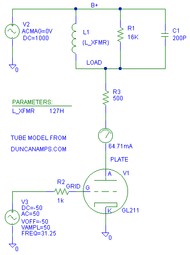
I went to www.DuncanAmps.com and downloaded a GL211 model so I could play with the inductive load line. Mikey wanted to see what what the load line did with a 16 K impedance with 27 H and 127 H of primary inductance.
This is the model I drew up to make these plots:
L1 is the primary inductance of the output transformer.
R1 is the reflected speaker load resistance (AKA: reflected primary
impedance or plate load impedance).
R2 is a grid stop resistor.
R3 is my guess for the DCR of the primary of the transformer.
C1 is my guess for the capacitance of the primary of the transformer.

I won't be varying R3 and C1 in the plots below as I vary both the primary inductance and the reflected load impedance. If we wanted to, we could design a transformer that makes R3 whatever value we want.
Keep in mind that C1 does not affect the phase shift at low frequencies. C1 is just there to remind us that we need to keep an eye on the high frequencies too while we are adjusting the low frequency performance.
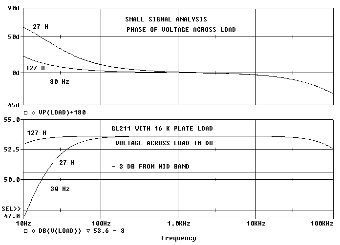
First, lets look at the small signal response.
Keep in mind that this is just the small signal (low power) frequency response. It will not tell us how the amp performs with a full power signal input. At the end of this web page, I have an overview of the differences between large and small signal circuit analysis.
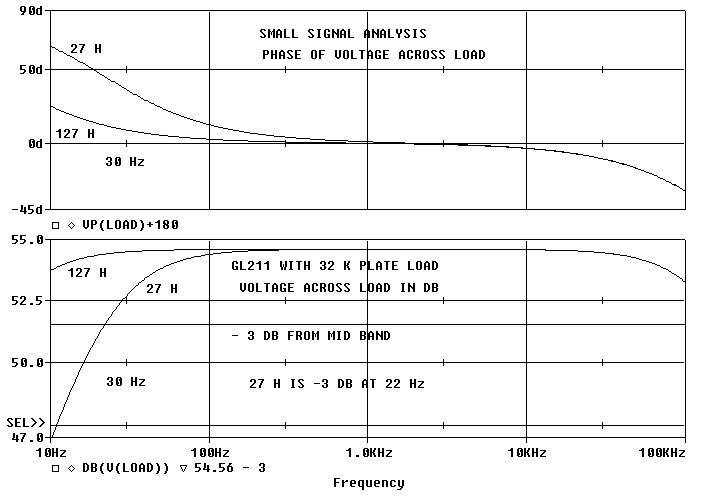
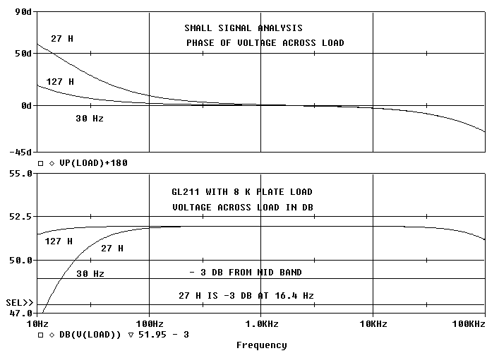
Notice that the gain and phase response is changing at 30 Hz more with a 27 H primary inductance than with 127 H.. The change in performance with a 27 H primary inductance does not look that drastic. With 27 H of primary inductance, the low frequency response is 3 dB down at 20 Hz. This normally would not be considered to be "bad."
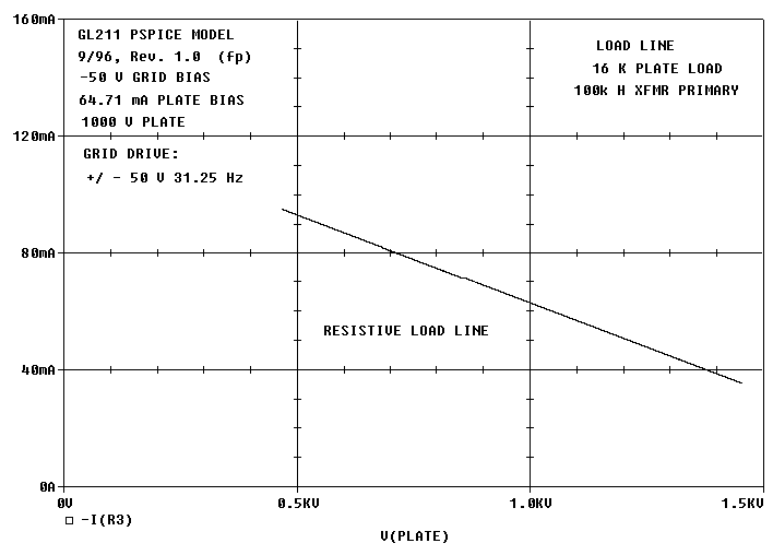
Now let's check the load lines
We are now starting to look at the large signal analysis. This is where the non linearity of the tube and the limitations of the bias point starts to come into play. The load line shows some of the practical/ "real world" issues in the design..
For a reference, I set the primary inductance to 100 k H so we can see the resistive load line. I can do this trick because the circuit model will let us use unreal values (this is both a good and bad feature.)
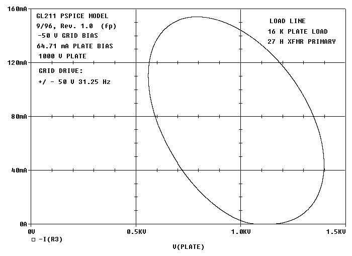
Now we'll look at the full output power load line with a 127 H primary
inductance.
This is full power because with any more grid drive voltage into the
GL211, we will be driving the grid positive. This is not too bad of a load
line.
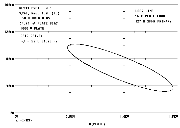
Note: When I am saying -50 V grid bias with +/ - 50 V drive, the grid
is going from 0V down to -100V, or -50V with +/ - 50V excursions around
the -50V bias point.
Next we'll change the primary inductance to be 27 H. The grid drive voltage is staying the same. This load line does not look too good. It spends a lot of time down near zero plate current. Remember when we don't have any plate current, we can't control the output, we can't drive the speaker and we get distortion. This is because the tube is spending all it's hard earned bias current to drive the primary inductance instead of the primary load impedance (the speaker.)
Let's look at the calculated distortion products from
the GL211 model
The plots are with 27 H and 127 H primary inductance
with a 16 K primary load.
Notice that the 127 H primary inductance with "full input power" to
the grid generates lower and fewer harmonics from the tube than with the
27 H. This is because the magnetization current of the 27 H is driving
the tube into cutoff (current clipping.)
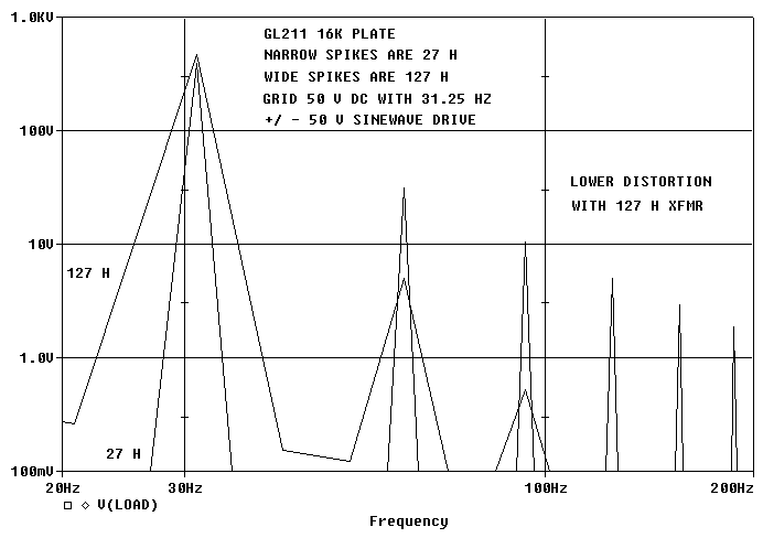
Because the 27 H primary inductance tilts the load line into an larger ellipse, the 27 H primary inductance causes the amplifier to go into cut off (run out of drive current/ or "current clip") sooner. Since the amplifier is going into cut off, it will have more nasty harmonics than one not going into cut off.
I did run a sweep with a 100 k H primary inductance. The distortion products were only 3 to 4 dB lower than with the 127 H primary inductance. I did not include the plot because it was too difficult to read..
I'm using a 31.25 Hz sine wave for the test because:
1. It has a period of 32 milliseconds which is a nice number to use in the model.It does not matter if your speaker does not go down to 31.25 Hz or not. If you are sending low frequency information to the amplifier, the amplifier will make the plate voltage move. If the plate voltage moves, the tube must spend bias current to charge and discharge the primary inductance as well as the actual primary load impedance. If the plate voltage or current "clips" because of low frequency plate excursions, the sound will suffer.
2. It is near the lowest normal musical frequencies.
3. I did not want to hear complaints about 20 Hz isn't a realistic frequency if I used 20 Hz.
To prevent the 27 H from causing distortion, let's just roll the output
tube's grid drive off at low frequencies. I went to the model and made
the drive +/ - 25 V instead of +/ - 50V peak. This is what should happen
to the distortion if we half the 31.25 Hz drive (output reduced by 6 dB):
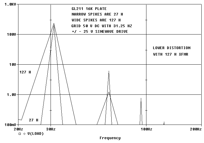
Yes the distortion goes down with less output. But the 127 H primary impedance still has less distortion than the 27 H.
| Peak Grid Volts | 25 | 25 | 25 | 25 | 25 | 25 | 50 | 50 | 50 | ||
| Reflected load impedance (ohms) | 8000 | 8000 | 8000 | 16000 | 16000 | 16000 | 16000 | 16000 | 16000 | ||
| Primary Lp henry | 27 | 127 | 100k | 27 | 127 | 100k | 27 | 127 | 100k | ||
| Primary Peak AC Volts | 174.7 | 196.5 | 197.6 | 201.5 | 237.2 | 239.3 | 393.6 | 473.8 | 477.9 | ||
| % THD | 2.875 | 1.087 | 1.000 | 3.070 | 0.502 | 0.360 | 8.528 | 1.041 | 0.747 | ||
| Power out watts | 1.91 | 2.41 | 2.44 | 1.27 | 1.76 | 1.79 | 4.84 | 7.02 | 7.14 | ||
| Power in dbW | 2.80 | 3.83 | 3.87 | 1.03 | 2.45 | 2.53 | 6.85 | 8.46 | 8.54 | ||
| Harmonic | Percent Distortion | Percent Distortion | Percent Distortion | Percent Distortion | Percent Distortion | Percent Distortion | Percent Distortion | Percent Distortion | Percent Distortion | ||
| 2 | 2.857% | 1.085% | 0.998% | 3.046% | 0.501% | 0.359% | 7.936% | 1.034% | 0.744% | ||
| 3 | 0.312% | 0.076% | 0.067% | 0.376% | 0.026% | 0.016% | 2.668% | 0.112% | 0.069% | ||
| 4 | 0.046% | 0.007% | 0.006% | 0.062% | 0.002% | 0.001% | 1.277% | 0.016% | 0.008% | ||
| 5 | 0.008% | 0.001% | 0.001% | 0.012% | 0.000% | 0.000% | 0.735% | 0.003% | 0.001% | ||
| Harmonic | Distortion in dB | Distortion in dB | Distortion in dB | Distortion in dB | Distortion in dB | Distortion in dB | Distortion in dB | Distortion in dB | Distortion in dB | ||
| 2 | -30.9 | -39.3 | -40.0 | -30.3 | -46.0 | -48.9 | -22.0 | -39.7 | -42.6 | ||
| 3 | -50.1 | -62.4 | -63.5 | -48.5 | -71.6 | -75.9 | -31.5 | -59.0 | -63.3 | ||
| 4 | -66.7 | -82.9 | -84.3 | -64.1 | -94.7 | -100.4 | -37.9 | -75.8 | -81.4 | ||
| 5 | -81.9 | -102.0 | -104.6 | -78.5 | -116.7 | -127.3 | -42.7 | -91.3 | -98.7 |
How does the low frequency load line affect the high frequencies?
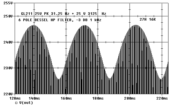
As the load line varies, the tube characteristics (gain) will vary. This variation causes intermodulation distortion (IMD). To keep this example reasonable, the grid drive was set to be +/ - 25V at 31.25 Hz and +/ - 25 V at 3125 Hz. This results in a +/ - 50 V waveform at the grid of the 2A3 which is the same as what we had at just 31.25 Hz.
To see the effects of the variation in tube gain I put a buffered filter
on the load to strip out the 31.25 Hz.
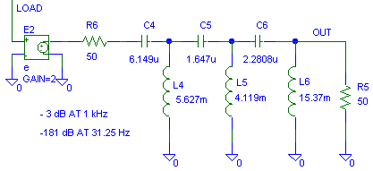
With 27 H, the 3125 Hz waveform is modulated by the 31.25 Hz signal. The 3125 Hz signal varies from 246.6 V peak to 225.9 V peak or 20.7 V peak to peak modulation.
Even with 127 H primary inductance we can see some distortion. The amplitude varies from 243.1 V peak to 234.9 V peak for 8.15 V peak to peak variation (a 2.54:1 improvement.)
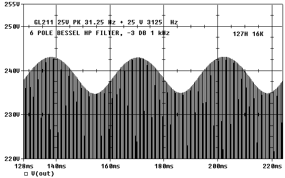
With the 100,000 H plate choke, the amplitude varied from 242.5 V peak to 235.5 V peak for a 7.0 V peak to peak variation. I'm not showing the plot for 100,000 H because it basically looks the same as the 127 H plot.
What about the phase shift caused by the speaker load?
So far, we have been just talking about the low frequency performance of the tube and transformer with a resistive load. The phase angle of the speaker impedance actually does change at low frequencies. Doesn't this change affect the load line and cause distortion?
To answer this question, lets throw out any problems from a poorly designed crossover networks and consider what happens if we drive just a single driver. This is the impedance plot an 8 ohm wide range driver:

Notice that the impedance never drops below about 110% of the voice coil resistance. Even at DC, the speaker will have at least the voice coil resistance as a limit of how low the impedance will go.
When a speaker does go into low frequency resonance, the impedance goes up towards a lighter load as the phase is shifting from the resonance!
The phase angle of the load from the speaker is changing, but it is changing at a point where the total impedance is higher than normal. Because the impedance is high at the speaker resonance, the phase shift does not mess up the load line. This is because the speaker is not drawing enough out of phase current to drive the tube closer to cut off (current clipping.)
What does the primary load impedance do to the load line?
So far, the phase shift of the transformer primary inductance seems to be the sole problem. What if we just change the primary load impedance and keep the primary inductance the same?
Here is the load line with a 27 H primary and a 32 k reflected impedance and a 8 k reflected impedance:
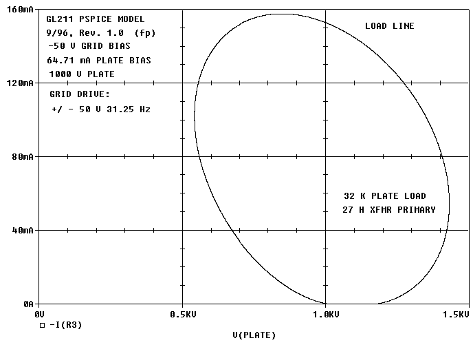
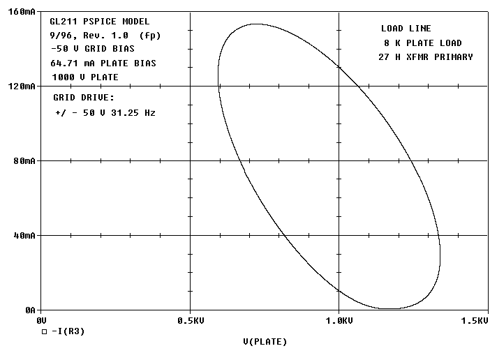
Notice that the tube is still going into cut off (running out of drive current) with different reflected primary impedances (plate load impedances). The 27 H plate inductance is still drawing too much current.
Lets look at the small signal analysis with a 32K plate load and 27 H primary inductance. It still does not look that bad. The voltage gain from the input of the tube to the plate load dropped with an 8 k load. This drop in voltage gain with an 8 k load is expected. Just as the slight increase in voltage gain with a 32 k load is expected.
The - 3 dB point did not change much with a 27 H primary inductance as the load impedance changes. This is because the small signal -3 dB point is dominated by the plate resistance of the tube.
Well, we varied the load impedance with a 27 H primary. Now lets see what happens to the load lines with a 127 H primary:
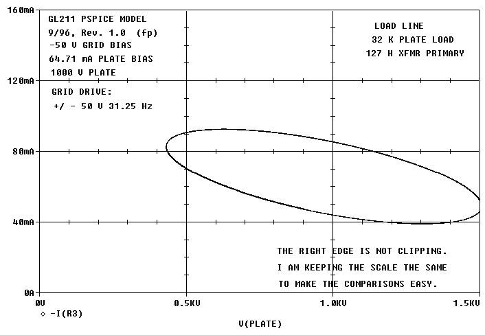
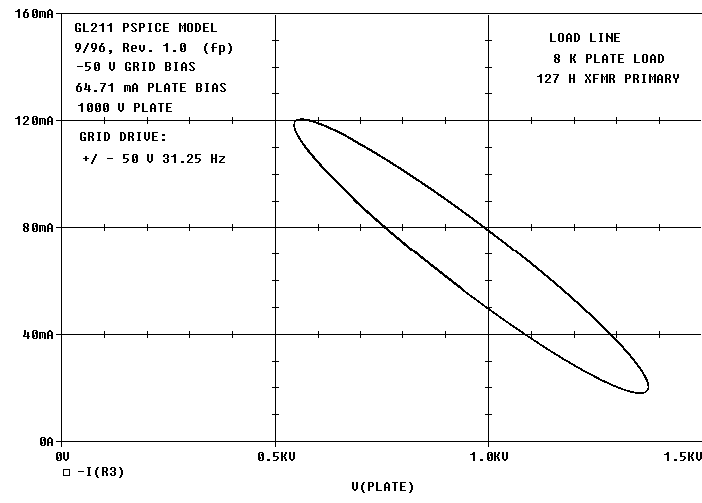
With the 127 H primary inductance, both the 8K and 32K load have current to spare before the tube goes into cut off. With the 27 H primary inductance, the 27 H is sucking up all our bias current with 8 k, 16 k and 32 k primary loads.
With 27 H, the load line is nasty. With a 27 H primary if there is any low frequencies making it from the preamp to the output transformer, I would expect the sound to be a bit nasty too. These low frequencies can be wanted (drum/ organ/ piano etc.) or unwanted (record warp.)
Appendix A:
Keep in mind that we are looking at both large signal and small signal models for the tube amplifier model above.
The small signal model does not know about:
1. Distortion. The small signal model is distortion free.
The small signal model will not know about:
1.1 Cut off (running out of bias current in the tube),
1.2 Clipping (running out of voltage swing in the circuit),
1.3 Grid current (distortion in the drive circuit for the tube),
1.4 Changes in the plate resistance with bias,
1.5 Distortion in the voltage gain of the tube,
1.6 Distortion in the current gain of the tube,
1.8 Distortion in the capacitors,
1.9 Distortion in the transformer
1.10 Unintentional coupling between magnetics
1.11 Unintentional capacitive coupling etc.
2. The circuit model does not know about practical aspects of the design.
The circuit model will not know about:
2.1 Power dissipation (you can put 1 kW into a 3 W plate or a 1/4 W resistor,)
2.2 Corona and arcing,
2.3 Current limitations (you can put 10 amps DC through 50 mA choke without saturating it,)
2.4 Voltage limitations (you can put 1000 V on a 50 V part,)
2.5 GIGO (Garbage In, Garbage Out.) The circuit does not know if you are asking the right questions or have included enough circuit detail. If you ask too simple of a question (too simple of a circuit), the answer may be faulty. If you ask too complicated of a question (too complex of a circuit), the data may be too hard to figure out. The circuit analysis will not tell you if you are asking the wrong question or looking at the wrong data point.
2.6 Part variations. The model is for a nominal part. The model does not know about variation between the parts unless you specifically test for the variation
2.7 Layout and construction cross talk. The circuit model does not know if you placed the B+ transformer winding right on top of the grid of your input tube
2.8 If we use an ideal linear voltage or current source with the large signal analysis, we can see what the perfect part will do. However, we can fool ourselves because the part we buy from our vendor is not perfect.
2.9 The model and the modeling programs do have mathematical limitations. The computer only has so many digits it can calculate accurately. This number varies depending on how you set the program up. In the end, we still have to build the circuit and measure it. But modeling can save us some very embarrassing mistakes.
3. The small signal model is good for dealing with frequency response analysis.
The small signal model allow us to:
3.1 Have fast calculations of the circuit performance. Because the small signal model is simple, it runs faster.
3.2 Tuning up or tuning out frequency response problems.
3.3 Solving problems with ringing in LC tanks.
3.4 Small signal stabilization of servo loops.
4. The large signal model is good for modeling the real time circuit with all the distortions your model accounts for.
With the large signal model we can calculate:
4.1 Distortion in the circuit,
4.2 Power dissipation in parts,
4.3 Start up and power off stresses
4.4 Load lines
4.5 Overload recovery response
4.6 Step response of servo loops
4.7 Most things we would use a scope or volt meter to debug etc.
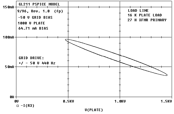

With 27H and 16K reflected load, there is some fattening of the load line even at 440 Hz.
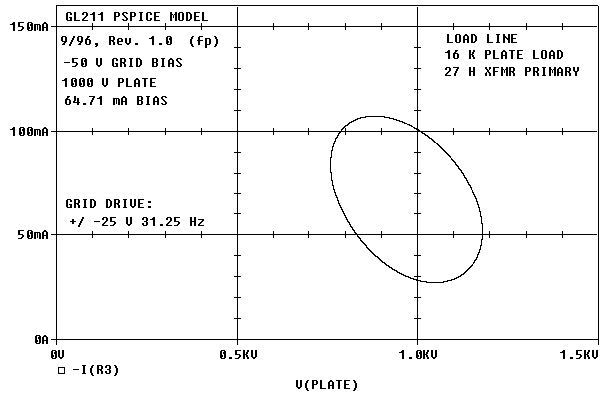
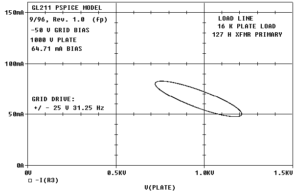
At 1/2 input drive to grid, the load line is still significantly tilted
with 27H of primary inductance.