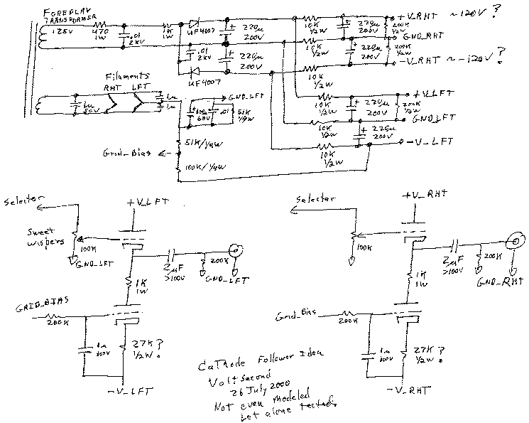
A cathode follower rebuild for the Foreplay preamp.
Standard Stuff:
This is not a product offered for sale. It does not have product
support.
High voltages are present in this design, build a copy at your own
risk.
1-SEP-00, It's making music.
Current design status:
* Filament snubber is installed. I did not A/B this change. It was difficult to fit in and dress the leads neatly on the original Foreplay, so I was lazy and put it in on the first build pass. On 5 mV /div on a 20 MHz scope, you can't see the output noise.Planned changes:.
* 86K resistor was installed in series with standard 100K volume pots to make a shunt volume control. The shunt volume control was a definite improvement. 86K was chosen because I had two 86K metal film resistors laying around. The schematic shows a 47K. I still have too much gain, I may add a two resistor 10 dB pad.
* 4.7 uF 630V SCR coupling caps (solid leads) were installed to replace the standard Foreplay caps. This also was an improvement just like in the Foreplay.
* The 0.01 uF HV snubber caps are installed with 630V polypropylenes. I usually use ceramics for this. Strange, it got easier to locate quiet percussion instruments, but the vocals were not as sharply defined. I'll let the circuit burn in and re-listen. If it does not improve, I'll put in my surplus 0.1 uF film and foil for C2 and a 0.01 Radio Shack Z5U for C1. With the 0.01 uFs on the HV, you could see the filament voltage clean up on A4, A5, B4, B5 connections! But the waveform is still not a pure sinewave like when I put the 0.1 uF in the Foreplay.
* An active load with a turn-on delay for the tube bias was installed. Click here to see Circuit for the Chaperone current source.
I used 470 uF 35V for C1, the delay capacitor and 180 uF 63V for C2, the current rise time capacitor. All I was expecting was a turn-on delay and less of a turn-on thump. The speakers are now silent even with my ear up to the cone, before there was a little buzz and hiss with my ears against the speakers. The fuzziness around vocals and some instruments was greatly reduced with the current source. However, the sound stage is now set back further and is not quite as wide. I don't remember the sound stage well enough from before to tell if the fuzz was removed if the sound stage would be the same size. I'm making the changes too fast and only get to listen after breakfast during the week.
* Sweet Whispers upgrade is installed. It is cleaner with the Sweet Whispers.
* Upgrade Single Series Stepped Shunt Stepped Attenuator.For kicks, here is where I started. I apologize for the image quality, it's hard to write neatly on napkins.
* Check to see if a resistor is needed in the cathode to suppress high frequency oscillations. Most cathode/emitter followers I've seen need them. My scope does not go high enough in frequency to see if there is a problem.
* Think of a better name than Chaperone. My wife does not like the Foreplay name, she calls it the Blue Preamp because it is painted with blue speckle paint. The new one is called the Brown one for the same reason.
* Add a 0.01 uF from the negative side of C3 to chassis ground to see if C3 and C5 are radiating noise into my current source.

This is where it ended before the modifications started. The reference numbers for the parts will be changing soon so they match the order they appear in my layout.
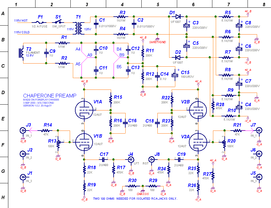
20-Aug-2001 Changed picture to show where safety ground
must attach. The chassis should also go to safety ground.
The long sad design story
After doing some modeling on the napkin sketch, I decided that the spare 1/2 tube was best used as a capacitive multiplier and not as a current source nor as two cathode followers in parallel. Here is the actual power supply I used.
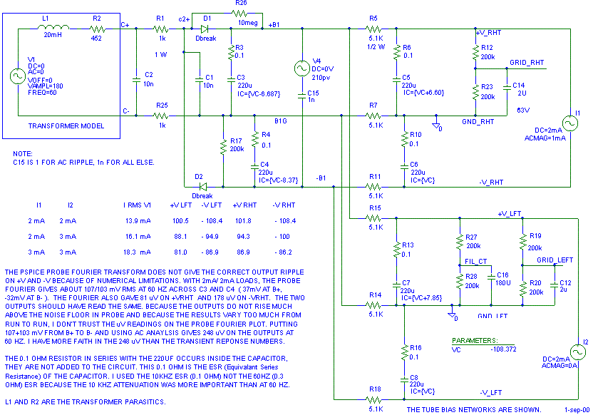
The purpose of this complicated power supply is to eliminate the crosstalk from the left to right channel through the B+ and B-. The following Pspice output shows the ripple induced on the power supply rails with 1 mA ripple from I1 (1V output in to a 10K load.) The levels are nothing to worry about.
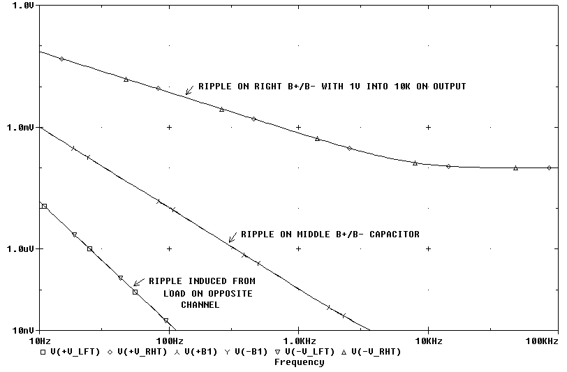
Lets check the noise from the power supply. The AC analysis says the actual 60 Hz ripple is 235 uV on the caps that attach to the tubes. With a power amp voltage gain of 30 dB, 100 dB SPL re 2.83V speakers and a target noise floor of 20 dB SPL out of the speakers, we can estimate how much noise is allowed from the output of the preamp:
*** 20 dB SPL - 100 dB /2.83V = -80 dB re 2.83VIf we model the preamp with 1V noise on the power supply rails, we need 1V * 8.9 uV/235 uV = 38 mV coming out of the preamp.
*** 2.83 V * 10^(-80/20) = 283 uV noise allowed out of power amp.
*** 283 uV * 10^(-30/20) = 8.9 uV noise allowed into power amp (noise allowed out of preamp.)
*** 20*log(8.9 uV out /235 uV noise on caps) = 28.4 dB minimum power supply rejection.
Should we use the extra 1/2 triode as a current source or as a capacitive multiplier to filter the B+ so we meet our 9 uV (38 mV with 1V on B+) output goal?The Big question: How to use extra triode in each tube?
Here is the the model I used to compare the circuits. (Tube models curtsey of www.DuncanAmps.com. ).
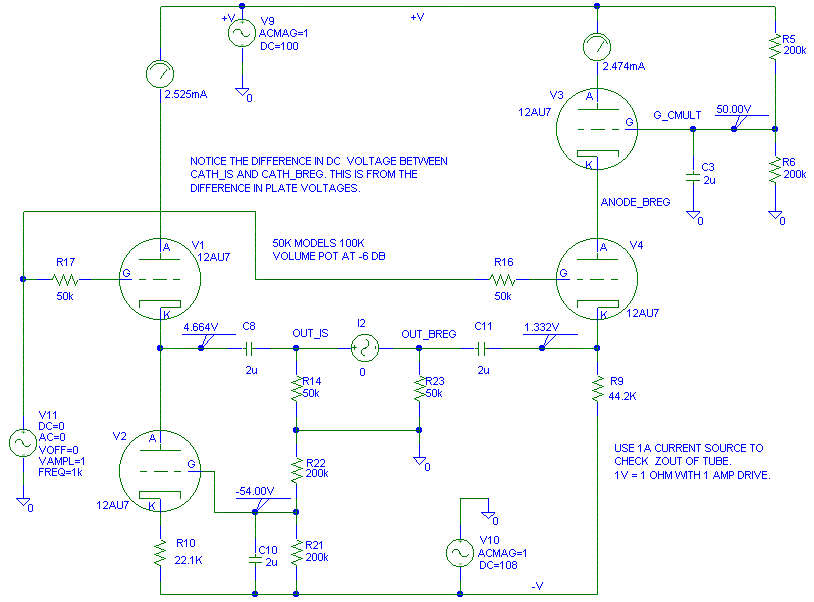
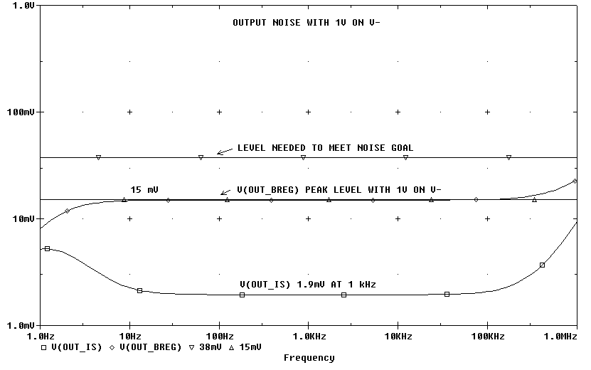
First, lets put 1V of ripple on the B+ and see what happens to the outputs. The circuit with the current source sends most of the B+ noise right through to the output with a bit more than 23 dB attenuation. The circuit with the capacitive multiplier knocks the B+ noise down a factor of 47 dB. The 15 mV (-36 dB) reference line is to help compare the B+ power supply rejection to the B- power supply rejection. The circuit with the capacitive multiplier meets the B+ ripple specification, the current source driven tube does not.

Now lets put 1V of noise on the B-. The I source works much better here than the capacitive multiplier. However, the capacitive multiplier output V(out_breg) meets the ripple specification with 1V on both B+ and B-. The I source only meets the ripple specification with 1V on B-. If we want the extra ripple rejection on B-, just add a C4S current regulator to the circuit with the capacitive multiplier. At this point, using the extra 1/2 tube as a voltage regulator/ capacitive multiplier looks like the way to go.
Now lets put 1V on the input and look at the output distortion into a 50 kohm load. The current source version works 4.8 dB { = 20*log(52uV/30uV) } better than the capacitive multiplier. However; all of the distortion looks like 2nd harmonic (which no one really cares about in audio) and 52 uV of second harmonic translates to be 85 dB down. (pretty inaudible). From these curves, I'd rather have better B+ power supply rejection.
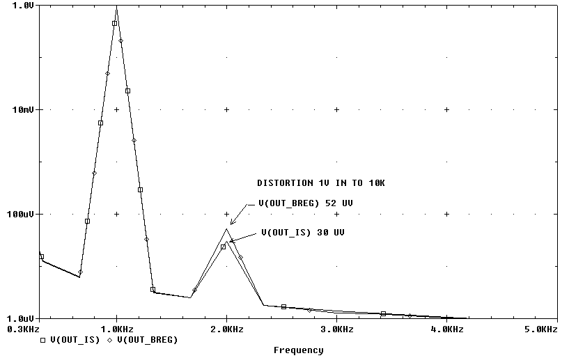
Originally I only got 5 dB difference in the second harmonics in the Fourier analysis. I played with the analysis settings and got the second harmonic to be higher above the numeric noise floor and saw 16 dB difference between the two set ups. Then I re-ran the calculations and was back to 5 dB difference. The distortion numbers on the second harmonic are so small, I don't know if the model reflects real life. I am not just talking about the tube model, I am talking about how linear all the other parts in the design are too.
If you want that last bit of distortion removed, install a C4S to feed the output cathode. Try it with out the C4S first.
Note: I can't find any more 1/8" ID rubber grommets for the transformer mounting, I had to use vinyl ones. I like the rubber grommets much better than the soft vinyl ones. I wish Radio Shack carried rubber instead of soft vinyl grommets.
27-Jul-00 First version 15-Sep-00 last update