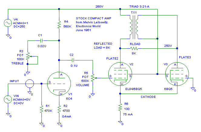
Several people are sending me questions about the Compact Amp by Melvin
Leibowitz (Electronics World, June 1961.) I have redrawn the circuit and
I am showing it below. Usually when more than a two people are asking me
reasonable questions about the same thing, I'll consider putting up a web
page about the topic to share any ideas I have..

One of the aspects of this amp is that it has a very high output impedance because it is a pentode output with no feedback. If it is driving a single voice coil speaker, we're in good shape. If we have a speaker with crossovers, we're toast. The speaker's input impedance swings will cause major frequency response issues.
Note:Some studies have shown current fed speakers have lower distortion than voltage fed speakers, current fed speakers just have a few issues at the low frequency resonance points. One issue is that the amps driving the speakers tend to voltage clip easily.
One thing this amp could use is a CCS for R6. Differential amplifiers
(long tail pairs) need a fairly high impedance on the cathode to ground
connection to keep the distortion under control. Lets discuss a CCS for
R6 first.
I pulled the model of an EL34 from Duncan Amps to model what the cathode voltage does when driven in a Compact Amp style circuit.
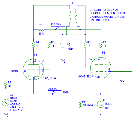
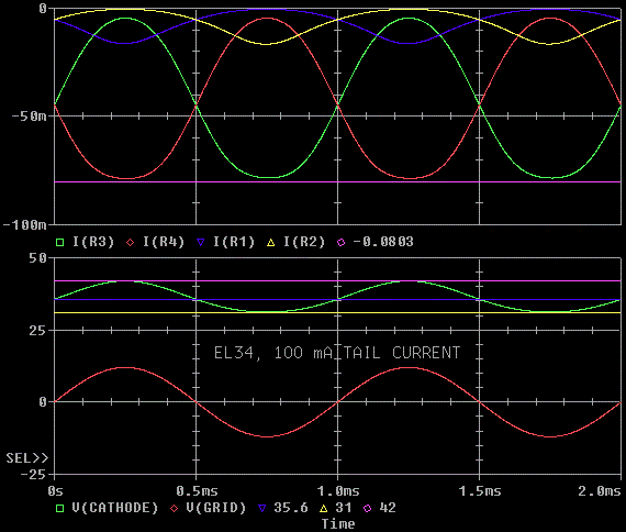
The cathode voltage moves up about 18% and down about 13% when the plates are driven into clipping. This tells us a CCS on the cathode will need about +/- 20% voltage compliance.
Lets do the same experiment on a 2A3.
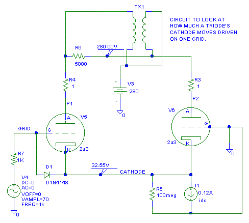
Wow. On a triode the cathode moves nearly +/- 100% This makes a CCS
design even harder for a triode than for a Pentode.
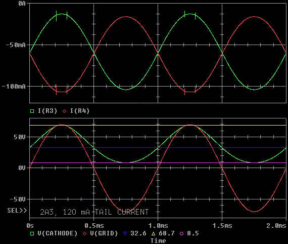
From the PSPICE model we see that the 2A3 has 33V on the cathode. With 33V across the CCS at .12A it will dissipate 4 watts.
From the 2A3 data sheet, the cathode should have been at 44V so the dissipation would be 5.3W. This discrepancy isn't too surprising in a triode model.
If we will be using a solid state CCS, we'll have to keep an eye on the temperature rise of the pass transistor. A transistor dissipating 4 to 6 W requires serious heatsinking. . . remember that a TO-220 with no heatsink is only good for about 0.5W.
We'll also have to use a CCS with a low voltage drop across it. This is because the cathode is dropping down to 8.5V. If we cascode the CCS for higher output impedance, we increase the risk of clipping or will require a fancier CCS.
A brute force Passive CCS: High volts and a large HOT resistor.
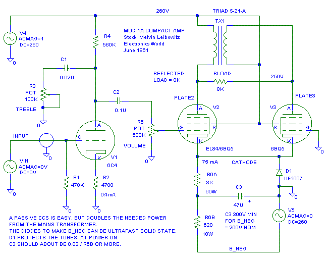
This technically isn't a true CCS, but it can work about as good as a solid state CCS on a long tail pair. Instead of running R6 to ground to bias the tubes, we run it to a voltage equal to the negative of B+. This "Passive CCS" means the HV winding of the mains transformer has to put out twice the current and you'll need a duplicate of the positive B+ capacitor bank to generate B_NEG. C3 and R6B provide the extra filtering we'll need to make the passive CCS quiet.
R6A + R6B = [V_cathode - B_NEG]/ I_Tail = [10V - (-260)]/ 0.075A = 3.6K.D1 is needed to protect the tubes at power up. Without D1, the tube are likely to do the "Arcy Sparky" dance from being over voltaged.
Use about 20% of the needed resistance for R6B and 80% for R6A.
Active CCS
Here is an example of a "protected" solid state CCS that should work
good for this application:
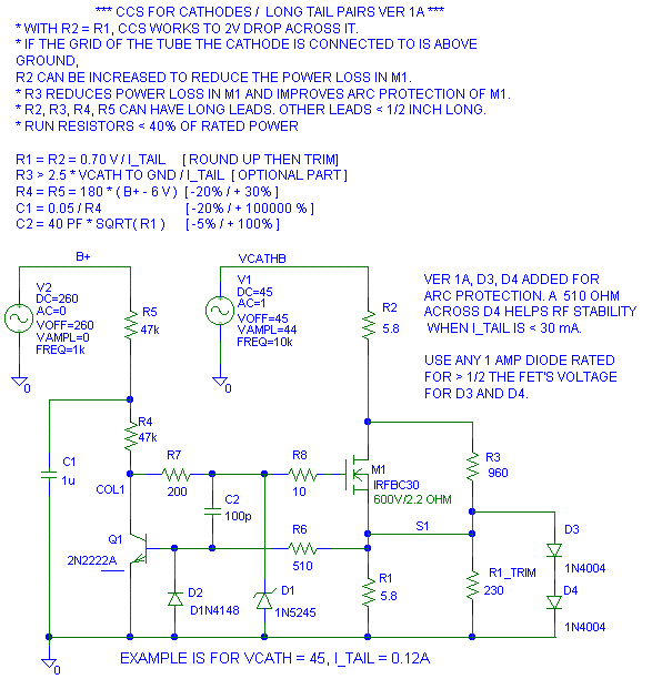
In ver 1A and ver 2A I added D3 and D4 for better arc protection. There is enough drain to source capacitance in M1 to damage the gate when there is an arc. D1, D3 and D4 work in concert to protect M1 and Q1. At light load currents the capacitance of these diodes makes a theoretical dip in the output impedance at 10 MHz. A 510 ohm resistor across D4 eliminates this dip. I don't know if it is a problem, but I'm telling what the fix is before you look. A fast diode for D3, D4 will recover from the arc faster than a 1N400x diode.
In the example above there will be 45V * 0.12A = 5.4W lost in the
CCS not counting R4 and R5.
5.8 ohm * .12A^2 = 80 mW in R1 and R2.I should note here, that with the DN2540 and other depletion mode FETs, you can not add R3 across the FET to reduce the power dissipation in M1. Adding R3 with the DN2540 messed up it's performance.
(45V - 1.4V)^2/ 960 = 1.98W in R3
(45V - 1.4V) * (0.12A - (45 - 1.4V)/960) = 43.6V * (0.12 - .0454A) = 3.25W in M1
(260V/2)^2 / 47K = 0.36W in R4 and in R5. (Use 1W resistors)
Another note: I am starting to like the IRFIBC30 over the IRFBC30. The newer isolated package is much more rugged mechanically than the old isolated packages. An isolate package still needs a thermal insulator under it (Don't use a " dry mount"). The magic of the isolated package is much harder to get shorts through the screw hole. The number of failures I've seen from the TO-220 tab to the mounting screw is scary. The "I" package fixes that. The down side is the "I" package has a much higher thermal resistance junction to case than the standard TO-220 package. This leads to a higher temperature rise for the same power dissipation.
OK, use that circuit in a sentence. . . (That's humor folks.) Here is what the conversion looks on a PP 2A3 like:
2A3 CCS'd Long Tail Pair Example
21-May-04 last update
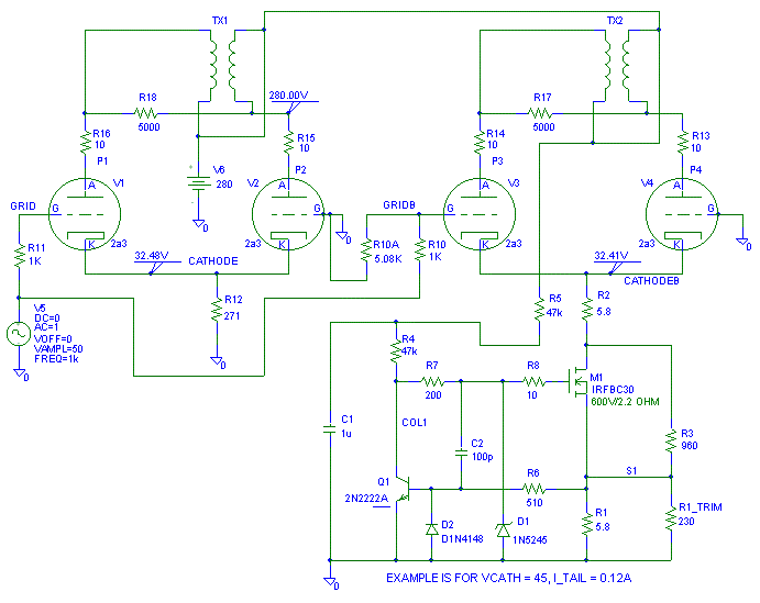
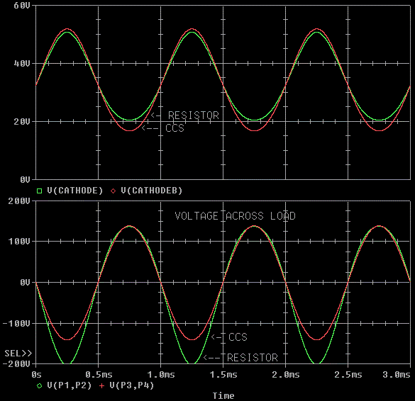
I had to attenuate the voltage to the CCS circuit to get the same voltage
on the load as the resistor biased version. Here's what a couple critical
voltages look like. P1 to P2 is the voltage on the load (speaker.) Notice
that the CCS'd circuit has less distortion and a bit more gain.
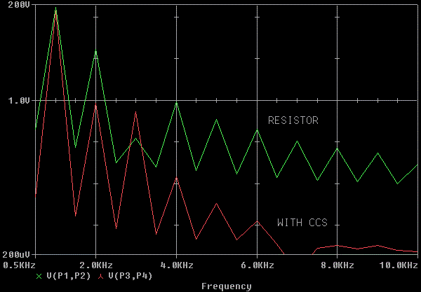
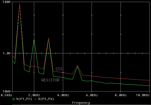
Here's the Fourier of the load voltages. Notice that the CCS'd version
is much cleaner at the higher harmonics where our ears are more sensitive
to distortion.
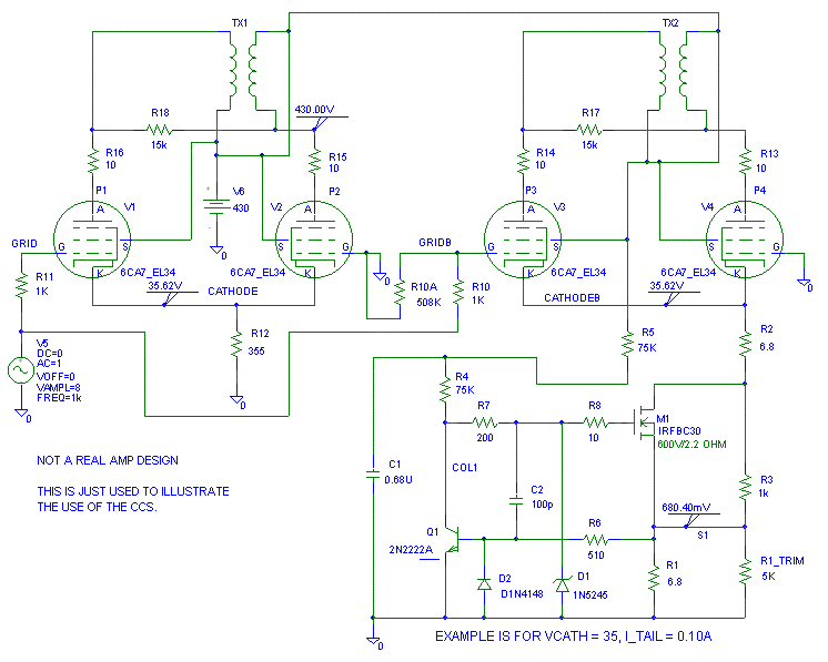
I just made up the 20W idle bias point and arbitrarily picked a class A load for the EL34. This is what the test circuit looks like.
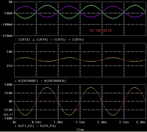
The models shows that the cathodes and plates look amazingly clean with
resistor or CCS bias.
The CCS doesn't seem to help as much as it did with the 2A3. Interesting.
In Gary Pimm's pentode circuit, the CCS on the cathodes worked magic. I'm
not sure what I am missing in this model. We're 95% sure the CCS should
help, but the model doesn't predict much help from the CCS. The 2nd harmonic
shows an improvement shouldn't be very audible.
What's
up with the too good to be true
numbers?
22-May-04
last update
These pentode numbers look too good to be true, so I wired the pentode
model up as a triode to get this circuit.
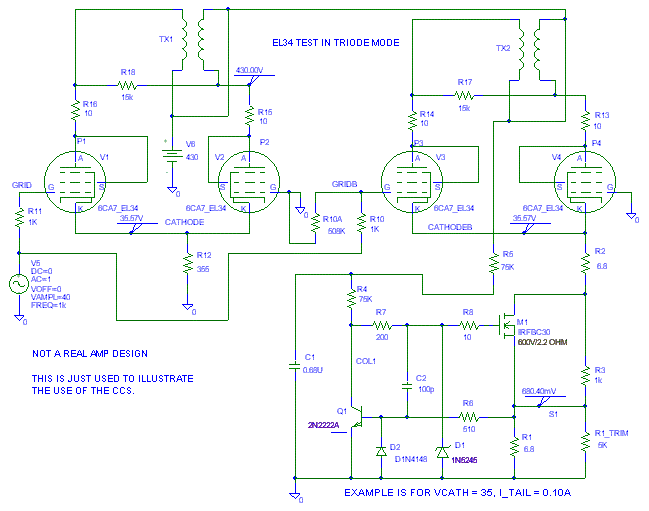
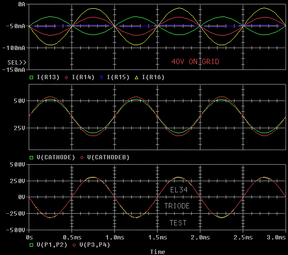
The voltages again look very very good. EXCEPT, tube V2 isn't doing
anything to help drive the load. V1 is doing all the work. V2's buddy (V4)
with the CCS on the "tail" is carrying it's fair share of the load. I'm
not sure what is going on here.
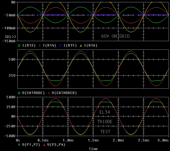
I cranked the input from 40V to 60V to show that the Resistor fed unit
goes into premature clipping.
STATUS: Confused.
The EL34 model used from the Duncan Amps page was 6ca7.inc V3 23/01/2004
If I work on this at a later date, I'll update the page if I learn anything new. The main purpose for this page has been accomplished: Show a CCS for a Compact amp.
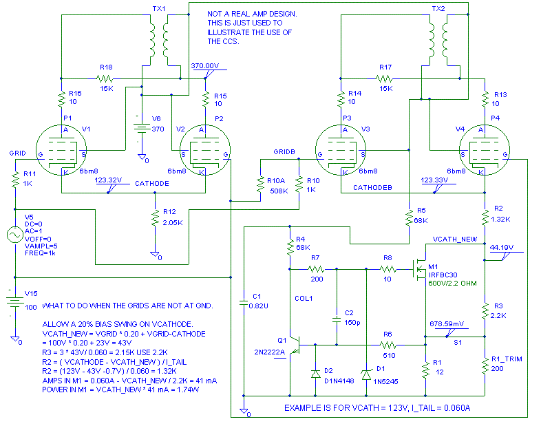
OK, how do we bias up the CCS if the driver is DC coupled to the output tube? If the driver is DC coupled to the output tube, the power loss in the CCS goes through the roof. The following is an example of how handle this.
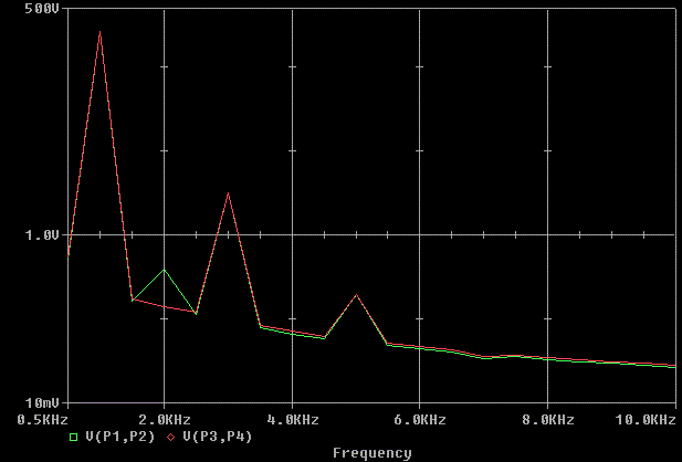
Here's the distortion plot just for kicks. Unfortunately at this point,
I don't fully trust the grid-cathode Pentode model I'm using in PSpice
so there is a chance this curve is better than what a real circuit can
do.
This is a slightly more complex CCS, but this one does not require bias from B+. C2 must be larger than version 1. Again it's untried, but I've done similar CCSs with success. V_cathode must be greater than 9V (Ok, 8V in a pinch) and the tail current must be large than 10 mA or the circuit will need serious retuning. You can operate below these values with a similar circuit, but you'd be better off using Ver 1 for Vcath < 9V.
Adding Q4 improves the performance of both Ver 1 and Ver 2. Q4 and R12 is why C2 needs to be a little bigger in Ver 2 than in Ver 1. You can use Q4 and R12 in version 1 if you make C2 bigger.

That's all for now. More to come when time permits.
This one isn't protected and isn't low voltage drop (works to about 9V), but it is simple. Again it is not cascoded in order to keep the drop out voltage as low as possible.
Because we can ground reference the CCS, we can use the B+ to make 12V
to run the CCS instead of using a 12V battery that drifts as it ages over
a couple years. Besides bypassing D1 and D2, C1 provides about a 1 second
turn-on delay and about a 5 second slow ramp up of the CCS current.
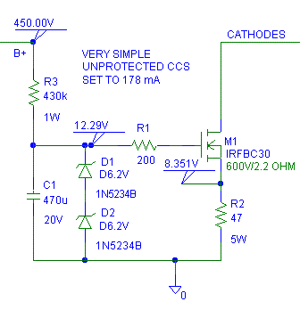
R2 = 8.4V/ I_Tail
R3 = (B+ - 12.2V)/1 mA = 1000 * (B+ - 12.2V)
Don't forget to put a heatsink on M1!
If you can, put a 15V zener (1N5245) from gate to source on the FET for a bit of protection.
I've recently built a version of this CCS for a different amp. It works great. See the link for the schematic. CCS for K-12M push pull pentode pair.
1. CCSs on both on the cathode of a long tail pair and on the plates at the same time are a bear to get balanced so it operates nicely. I've got a circuit in mind to fix this. I'll put it on this page when it looks viable.
2. Always unplug your unit, discharge the caps, measure the capacitor voltages (DC) before touching the unit.
3. Install at least two bleeder resistors on each power supply rail. These will keep the capacitor's dielectric adsorption from recharging the capacitors and give you a nasty shock.
4. GFCI's won't protect you if you get across the secondary side of the transformer.
5. All exposed metal has to be attached to safety ground. I've been shocked by a 115V wire that came loose and hit a floating chassis. I read the person who didn't ground the chassis the riot act.
6. Circuit have to be laid out for the bandwidth of the part you are using, not the bandwidth of the circuit. FETs have gain out to the FM band, so short leads are needed to make them behave.
7. Cascoding a CCS will raise it's output impedance. The down sides to Cascoding are an increased chance of RF and/ or audio oscillations and a larger minimum voltage drop across the CCS.