These circuits involve high
voltage. Try them at your own risk!
Last Update 5 Aug 07
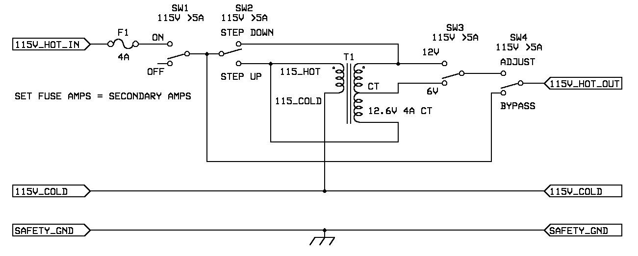
A variac (variable transformer) allows very fine adjustment of the 115V line voltage from zero and usually all the way up to 130V ac. We normally don't need that much range for continuous operation. We also don't normally need a super fine adjustment. What we typically need is an autoformer to change:
127V down to about 115V,
120V down to about 115V, and
110V up to about 115V or even. . .shutter. . .
105V up to about 115V

SAFETY ALERT
!
All wires but chassis will be at line voltage.
There is no safety isolation in an autoformer so don't touch the output
voltages.
Assume touching any wire of an autoformer may end your audio listening
pleasure. . .permanently.
Design Notes:
1. The (filament) transformer's secondary should be rated for at least 120% more current than what it is needed to deliver. This is for a few reasons. The top two are: First is we don't want the DCR of the filament transformer to mess up the line regulation. The second is that filament transformers can run hot, a 20% or more pad will cool them off a bit.By 20% I am suggesting that we should plan for 4A transformer if we are expecting 4A/1.2 = 3.3A in continuous use.
2. If you can get a 50/60 Hz primary rating for the transformer instead of a 60 Hz rating, do it.
3. If you can buy a 120V primary instead of a 115V primary, do it.
4. The fuse should be rated for the same or slightly less current than the transformer's secondary current rating.
5. The switches should be rated for higher current than the secondary's current rating. 2 times more is preferred. The switch voltage rating must be equal to or higher than the line voltage.
SW1 This is the standard on/off switch
SW2 Allows the autoformer to be as a step up or a step down.
SW3 Allows for the voltage adjustment to be about 6V or about 12V
SW4 Allows for 115V to go through unadjusted.
The switches can be omitted if you want to build a hardwired version of this.8. Use a grommet or other anti-abrasion device to keep sharp edges of the autoformer's enclosure from cutting into the input (and output) line cord's insulation.9. Remember to put strain relief on the wires going in and out of the box so if someone yanks on the cord, it doesn't pull on the internal wiring.
10. Dress all wires so that if the solder joint or wire nut comes loose, the wire doesn't spring out and short to chassis or anything else metal.
A. Unplug the box or amp this is built into from the wall socket.Hint: If you are adjusting a pair of dual mono power amps, build one of these for each channel for best performance.B. Hook your meter up before you apply power and set it to >=199V ac full scale for a 115V line voltage. Set the box's switches for step down.If built into an amp, first measure resistance from all audio input and output connections to the line cord's hot and neutral with the power switch in the on position. If it doesn't read open circuit, something is deadly wrong. If built stand alone or into an amp, with the power switch on, measurement resistance from chassis to the line cord hot and neutral. If it doesn't read open circuit, something is deadly wrong. Verify safety ground "in" measures zero ohms to safety ground out. Verify that the chassis measures zero ohms to the safety ground pin on the power plug. Note: Some amps don't ground chassis. Test / adjustment fixtures like this should always ground chassis. The black meter lead goes to 115V neutral.AT THE TRANSFORMER connections (not at the input and output leads), with no load on the output, use the red lead check that the 12V output side of the secondary is about 12V lower than the primary to secondary connection. Don't move the red or black lead with power applied. Unplug the unit, move the lead and turn the power back on. Spend a few seconds for safety, you won't regret it.
Example: the output should read 110V with 122V in.
If you wire the secondary wrong (backwards), the connection between the primary and secondary windings will read higher than the raw line voltage (134V out for 122V in). If this happens, unplug it and swap the ends on the secondary.
Remember, the primary always has one end hooked to line neutral.