Damping a circuit is to reduce the ringing in it. Dampening a circuit is to throw a wet towel on it (probably because it is on fire and you just got done pulling the wall plug.)
Star Trek is not the same any more once I had the difference pointed out to me that way. I can't keep a straight face when the say "put a dampening field on the Klingon vessel". What are they trying to do? Everybody knows Klingons don't like being wet so they are going to throw a field of wet blankets on them. No wonder they always react so violently to the dampening field.
Overshoot and ringing in a circuit is caused by having an under damped two or more pole network. This is an L and a C in a passive network, two L's in a feedback network or two C's in a feedback network. The feedback network can be intentional (feedback in an amp) or unintentional (parasitics.)
There are many ways to reduce overshoot. They all rely on removing energy from the tank that is ringing at the ringing frequency. If you remove energy at frequencies other than the ringing frequency, you'll have a loss in gain and/or efficiency of the circuit.
The page isn't done, but it should get you started with the concept of RC damping. All of the examples on this page were done with an output transformer. The same tricks and the same equations work with small intrastage and interstage transformers. When working with interstage transformers, expect the resistors and inductance values to be ten times larger and the capacitance values to be 10 to 100 times smaller.
The design method assumes that there are no other losses but those provided by the RC damping. This usually is a reasonable assumption. The method is not very sensitive to resistor or capacitor values. A 20% change in resistance or capacitance usually has no effect.
When damping a transformer in the audio signal path, use a decent quality damping capacitor. In an audio power supply, the damping capacitor can easily be a less expensive capacitor than the main filter capacitor (you don't need to use a film for damping if the B+ capacitor is film.)
Note: "Lossy Parafeed" works the same way, but there aren't any equations
to calculate optimum values that I know of.
Ringing from an LC tank can occur at the either end of the frequency spectrum in an audio circuit. At the upper frequencies, the L and C that are ringing may not be the values listed on the specification for the part. To debug the LC tank, it is usually best to drive the circuit with a fast squarewave and carefully add a small capacitor to the several points in the circuit while watching the ringing with a scope. It is almost always best to tune the transformer with it installed in the circuit it is used in.
When you add the capacitor, if the ringing changes frequency, you have found the tank that is ringing. If the ringing changes amplitude, you have not found the tank that is ringing and you are just masking the problem at the location where the scope probe is attached. If nothing happens on any circuit point, the capacitor is too small. Increase it by a factor of 10. Start with a small capacitor and work upwards in value. You are less likely to break something. Watch the voltage rating on the capacitor when you use it too. Don't put a 50V part on a 400V circuit.
Be very careful around high voltages. Holding the capacitor by the case insulation to touch it in the circuit is WRONG. Doing that can get you seriously hurt or electrocuted. If you are testing anywhere near the line voltage or high voltages, solder the capacitor in with the unit unplugged, test it, power down and then move on to check the next location.
LC tank ringing can occur with at low frequencies too. I'm not addressing this yet. The fixes are similar.
Once you find a point in the circuit that changes the ringing frequency, add capacitance to this point until the ringing frequency approximately halves (the period doubles (the time between zero crossings doubles)). A 50% change in frequency is the smallest value cap you'd want to trust for this test. A 3X change in frequency is about the biggest value you'd want to use.
Record the ringing period without the capacitor ( t_without_cap). Record the ringing period with the capacitor ( t_with_cap) and the record the added capacitor value (called C_add).
The parasitic capacitance can be found using the following equation:
C_parasitic = C_add / [ ( t_with_cap/ t_without_cap)
^2 - 1 ] - Scope probe capacitance (usually 10 pF)
Calculate the original parasitic ringing frequency,
F_orig = 1/ t_without_cap.
Now calculate the circuit inductance and characteristic impedance:
L_parasitic = 1/( C_parasitic * [2 * PI * F_orig]
^2 )
Ro = sqrt( L_parasitic/ C_parasitic) [Normally we
use Zo for this parameter; however, Zo is used elsewhere on this page for
something else. To to avoid confusion I am using Ro for the characteristic
impedance of the LC tank.]
Notes:
1. Another way to damp the tank is to determine Ro and add a resistor approximately equal to Ro across the inductor or in series with the inductor. A resistor across the inductor usually defeats the purpose of having the inductor in the first place. Usually the circuit losses are too high with the resistor in series with the inductor. However, sometimes this trick works just fine.Now that we know what the parasitics values are, we need to add an RC across C_parasitic. There are a set of formulas that are useful in calculating the best R value for a given C_damp. The calculations for optimum Rd (R_damp) and Cd (C_damp) were given in "Design Techniques for Preventing Input-Filter Oscillations in Switched-Mode Regulators", Powercon 5, May 1978 by R. D. Middlebrook. Use the nearest 20% part values for the sensitivity to the actual values is reasonably low.2. When you add C_add, if the amplitude changes but the frequency does not, you are not adding C_add to the tank that is ringing. You are attenuating the ringing.
3. If you are willing to add feedback (ARRGH! Sometimes feedback actually is good. Just don't over do it.), a small cap from plate to the grid of the tube with the ringing can sometimes kill the ringing. If the resistance to the grid is constant, this isn't too bad of a way of killing the ringing. This cap will have to be a decent capacitor material and properly rated for the worst case voltage the capacitor could see.
4. You can also damp an LC tank with a second inductor in parallel with the original inductor. The second inductor will have a resistor in series with it to provide the damping. The second inductor is usually 1/2 the value of the original inductor. In tube audio, this is usually a bad way to add the damping. I've seen it done in EMI filters.
5. Diodes can be used to damp LC tanks, this must be avoided in audio circuits for we don't want the sharp clipped edges the diodes will generate. Diodes used for "damping", if done right (it not easy to do right), can be used in the power supply of an audio circuit.
6. Sometimes people will kill the ringing by rolling the frequency response of the amplifier off so that the output does not ring. This does not always protect the output against power supply noise exciting the ringing or noisy tubes exciting the ringing. This roll off is not always bad, but be very careful using it.
n = C_damp/ C_circuitIn an audio transformer we usually care about Rd_opt_H which is the best damping for a step in input voltage.Rd_opt_H = Ro * sqrt[ ( 1 + n) * ( 2 + n)/ { 2 * n ^2} ]
Rd_opt_Zi = Ro * sqrt[ 2 * ( 1 + n) ^3 * ( 4 + n)/ { n^2 * (2 + n) * ( 4 + 3n) } ]
Rd_opt_Zo = Ro * sqrt[ (4 + 3 * n) * ( 2+ n)/ { 2 * n ^2 * ( 4 + n) } ]
Notes:
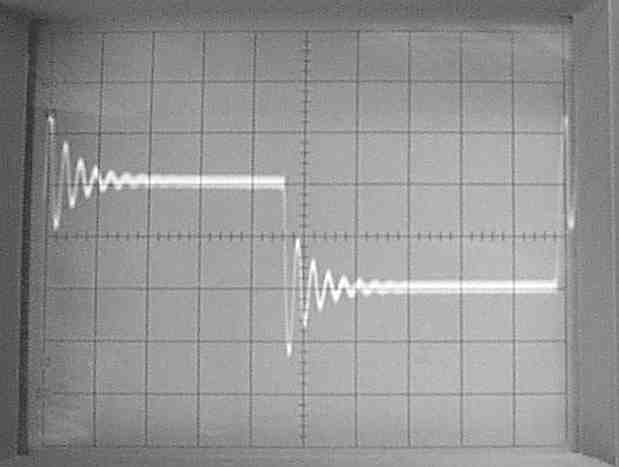
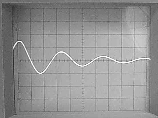
* The speaker was disconnected to get better readingsWith a square wave input into the amplifier, the 8 ohm output looked like this (2 V/ div 20 usec/ div):
and so that my dogs and I didn't have to listen to that awful squarewave.
* With one of my Radio Shack speakers connected, the ringing did not change in amplitude much because the speaker was inductive at the ringing frequency. The ringing change more with my main set of speakers.
* The 2A3 output tubes were the stock Valve Art.
* The cathode follower did not have any bypass capacitors attached to it to slow the rise and fall of the waveforms.
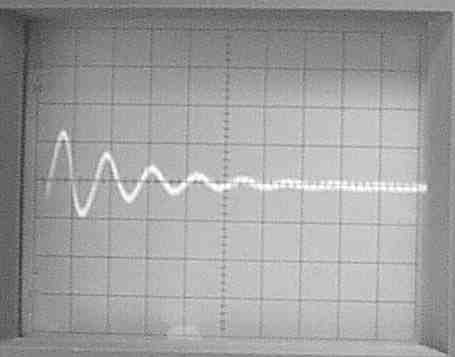
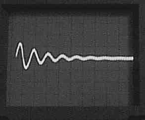
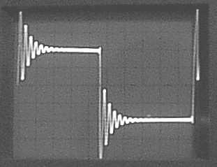
This is a close up of the ringing with no speaker load, but with 10
feet of speaker cable, on the 8 ohm output. This is not a stock
amplifier so don't go griping about the quality of the squarewave or dis'ing
Bottlehead products. I left the amp in this nasty condition just to get
pictures for this web page. The scope was on 2V/ div and 5 usec/ div. The
trace actually was fuzzy (RF pick up from a nearby AM station), the poor
picture quality is not the full cause of the fuzzy trace. Count the periods
using the second zero crossing, not the first. The second zero crossing
in this picture has a downward slope and occurs at "1 time division" or
at 5 microseconds. I count three rings in 18.0 usec on this picture.
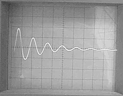
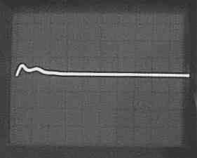
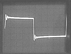
Now I've added a 10 nF mica capacitor across the 8 ohm tap. Notice that
the trace is thinner (less RF noise pick up) and the ringing is slightly
larger in amplitude and slightly longer in period. I count three rings
in 21.5 usec in this picture. (5 usec/ div)
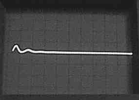
Now I've added a 0.1 uF across the 8 ohm output. The ringing has significantly
changed in frequency. I count two rings in 32.0 usec in this picture. (5
usec/ div)
0 n cap ringing was 18.0 usec for 3 rings or 6.00
usec for one ring (167 kHz)
10 n cap ringing was 21.5 usec for 3 rings or 7.17 usec for
one ring (139 kHz)
[not enough change]
The capacitor was a mica 5%.
100 n cap ringing was 32.0 usec for 2 rings or 16.0 usec for one ring
(62.5 kHz)
[more than double, a bit too much test capacitance.]
Capacitor was an X7R 10% ceramic.
Based on the 10 n cap:
C_parasitic = 10 n / ( ( 7.17 uF/ 6.00 uF) ^2 - 1 ) = 10 n/ 0.428 = 23.4 nFBased on the 100 n cap:
L_parasitic = 1/( 23.4 nF * (2 * PI * 167 kHz) ^2) = 38.9 uH
Ro = sqrt( 38.9 uH/ 23.4 nF) = 40 ohms.
C_parasitic = 100 n / ( ( 16.0 uF/ 6.00 uF) ^2 - 1 ) = 100 n/ 6.11 = 16.4 nFWhy the difference in the two calculations?
L_parasitic = 1/( 16.4 nF * (2 * PI * 167 kHz) ^2) = 55.5 uH
Ro = sqrt( 55.5 uH/ 16.4 nF) = 58 ohms.
1. Leakage inductance (L_parasitic in this case) changes with frequency.The calculations for optimum Rd and Cd were given in "Design Techniques for Preventing Input-Filter Oscillations in Switched-Mode Regulators", Powercon 5, May 1978 by R. D. Middlebrook. Use the nearest 20% part values for the sensitivity to the actual values is low.
2. Measurement error.
3. The zero crossings change a bit with Q, so the readings may be a little off.
n = Cd/ C_circuitWe care about H in this case so for n = 100 n/ 23.4 n = 4.37 and n = 100 n/ 16.4 n = 6.1Rd_opt_H = Ro * sqrt[ ( 1 + n) * ( 2 + n)/ { 2 * n ^2} ]
Rd_opt_Zi = Ro * sqrt[ 2 * ( 1 + n) ^3 * ( 4 + n)/ { n^2 * (2 + n) * ( 4 + 3n) } ]
Rd_opt_Zo = Ro * sqrt[ (4 + 3 * n) * ( 2+ n)/ { 2 * n ^2 * ( 4 + n) } ]
Rd_opt_H = 40 * sqrt( (1 + 4.37) * (2+ 4.37)/(2 * 4.37^2) = 40 * 0.8956 = 35.8 ohmsI've got a 51 ohm and a pair of 71.5 ohms to make a 35.8 ohms. The 51 ohms damped better, which we will soon see.Rd_opt_H = 58 * sqrt( (1 + 6.1) * (2 + 6.1)/( 2 * 6.1^2) = 58 * 0.879 = 51 ohms, a 42% difference in ohms.
All of these pictures were taken from a Paramour (01/18/01 mod status) with a cathode follower driving the grid of the 2A3, no speaker was attached, 3 meters of speaker cable were attached to the 8 ohm output. The scope was on 2 V/ division. If you can see the entire square wave, the scope was on 20 usec/ div. If you can only see the ringing, the scope was on 5 usec/ div. My speaker did not stop the ringing from occurring, but the waveform was harder to explain.
First let's see the unmodified ringing again:
Now lets add a 0.10 uF with a series 35.8 ohms (the non-optimum resistor
due to measurement errors.) The ringing is greatly reduced, but there is
a separate overshoot imposed on the ringing because the resistance is too
low.
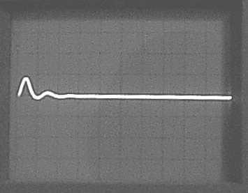
Now lets add a 0.10 uF with a series 51 ohm.
The peak ringing is is about the same, but there is no lower frequency
overshoot to speak of.
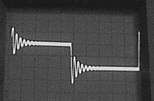
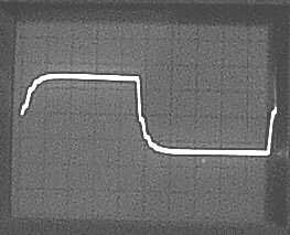
Lets look at the original squarewave and the final square wave with
the 51/ 0.10 uF damping. It looks kind of nasty with out the damping.
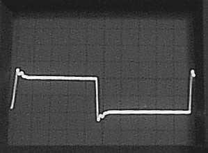
Now lets check the non-optimum 35.8/ 0.10 uF. This is quite a bit better.
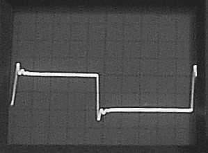
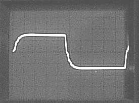
Now lets look at the calculated optimum 51/ 0.10 uF. This is better
yet.
Why is there still ringing?!
For every parasitic capacitor in the transformer, there is at least one high frequency ring it can generate. The three major capacitances in a two winding transformer are:Generally, you don't need nor want a capacitor 6 times the parasitic capacitance like I used in the example. 1X is about the lowest value that does any good. 3X usually is usually good enough. 3X times 16.4 nF is 49.2 nF.1. The effective capacitance across the input (primary).We only addressed the effective capacitance across the output. We did not touch the other two. Usually, a RC damper is not what you want to use on the bridging capacitance, a clamp on ferrite bead (possibly with more than one turn through it) is the better choice here.
2. The effective capacitance across the output (secondary).
3. The effective capacitance from the input to the output (the bridging capacitance).In a SET or interstage transformer, my gut feeling is we should leave the input capacitance alone. But I have not tried RC damping there. . .yet.
The only difference between 50 n and 65 ohms and 100 n and 51 ohms is the first peak is a bit higher with 50 n 65 ohms. With 100 n and 51 ohms, the damping will be less sensitive to changes in load (changes in the speaker in this case.)Rd opt = 58 * sqrt( (1 + 3) * (2 + 3)/( 2 * 3^2) = 58 * 1.11 = 64 ohms.
If you have an interstage transformer you are damping, you don't have to worry about changes in load that much so stick with about 1X to 3X c_parasitic for C_damp. In an interstage transformer the capacitance of the scope probe probably adds more capacitance than changes in the tubes will ever add.
What the no load output looks like with 50 n and 65 ohms for damping.
I'm kicking the scope gain up to 1V/ div 20 usec/ div just for better visibility. Remember, this is NOT the stock Paramour!
This is no load on the amp.
This is an 8.45 ohm dummy load on the amp. Notice that the resistive
dummy load really kills the ringing without adding RC damping.
This is the 8.45 ohm dummy load with a 0.1 uF 51 ohm RC damping. There
is a slight improvement in the ringing. Definitely not enough improvement
to justify adding the parts at this time.
This is my HornShoppe Horn loading the amplifier with no additional
damping. This horn uses a single Fostex driver with no crossover. As the
driver goes inductive at high frequencies, the damping for the output transformer
disappears. This is neither the amp's or the speaker's problem. It is just
the way things are.

This is my HornShoppe Horn loading the amplifier with a 0.1 uF 51 ohm
RC damping network added across the 8 ohm output. Here the RC is helping
with the ringing. Remember, most speakers are inductive at high frequencies
so you loose any damping they provide for the amplifier. A Zobel network
on the speaker can prevent the speaker from looking inductive at high frequencies
too. This RC output damping works in the same manner as the Zobel, but
it tuned to the transformer/amplifier, not to the speaker.
Unfortunately the frequency response out of the speaker does NOT always follow the voltage applied to the speaker inputs. We are not getting an acoustic square wave out of the speaker. However, the frequency response out of the speaker is proportional to relative changes in the voltage the speaker is being fed. So it may may help the sound if the damping were used on the output transformer, but it may not. The ringing may also affect the sound of the amplifier because the ringing is drawing current from the output device. This draw of current may or may not introduce an audible distortion.
If this were a transformer that drove another gain stage, reducing the ringing has definite benefits. This ringing may cause the next gain stage to clip and/or be over driven way before the normal audio signal would drive it to these levels. The high frequency ringing can also cause intermodulation distortion that could creep back down into the audio spectrum. The high frequency ringing can make the circuit more sensitive to outside noise sources like AM Radio stations and power supply noise. One the minus side, we already know resistors and capacitors in the circuit can adversely affect the sound of the amplifier. To damp the ringing, we'd have to add a resistor and a capacitor. If they are not of proper quality, the sound could suffer worse than if we left the ringing alone. It just goes to show: There ain't no such thing as free lunch.
This is how Rd and Cd are hooked up on the output.
This is a test schematic. We will be able to check the output impedance,
input current draw and output peaking as we play with part values.
In the following output, I swept Rd from 10 to 300 ohms with Cd = 100
n and RS = .001. Notice that best performance occurs at different Rd values
depending on which performance parameter we are concerned with.