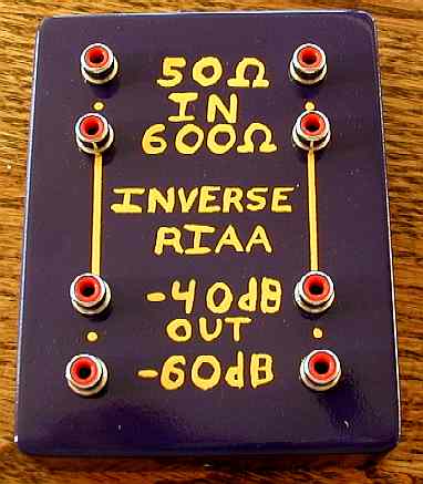
The end result looks like this (yellow hand lettering on a purple painted
box). The bottom has felt feet on it to keep from scratching table tops:

I added an electrostatic shield inside the box to help keep the channel
cross talk down. In the picture below, the signal inputs are on the bottom.
The insides with a brass electrostatic shield between channels looks like
this:
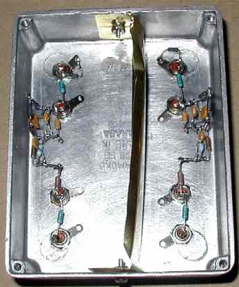
I used two resistors to make the 41.66K.
I used three resistors to make the 513K. I could have gotten by with
two resistors, but with three I could use what I had on hand.
I found a single 1.80 nF NPO cap that measured 1.79 nF
It took three NPO capacitors to get a 6.20 nF to within 1%.
I ran a brass divider between the two channels. The brass is bent on top and bottom so it presses against the top and bottom of the aluminum box.
I put it in a Philmore 1590BB Diecast aluminum box (4.68 x3.68 x1.33 $7.89 from Fry's electronics).
The first step is to prepare the box.
1. Sand the inside,
2. Screw the lid on, file the burrs off and then sand the outside.
3. Drill the 1/4 holes for the RCAs (0.75 inch from edge of box
and 0.75 inch apart.)
Since I sanded the scale off the inside of the aluminum box and used internal tooth lock washers under the RCA nuts, I decided not to tie the grounds together with a wire.
I did not make an effort to set the gain to exactly -40.0000000 dB. -39.xx dB was good enough.
First a discussion of errors in dB. An error of 0.1 dB (+1.16%) is really
pretty tight. Don't over react to the values you see in the plots. If we
consider a circuit where the gain is 100% proportional to the resistor
value, we end up with a table that looks like this:
| RESISTOR
VALUE |
PERCENT ERROR IN
RESISTOR VALUE |
ERROR
IN DB |
| 613200 | 20.00% | 1.584 |
| 562100 | 10.00% | 0.828 |
| 536550 | 5.00% | 0.424 |
| 521220 | 2.00% | 0.172 |
| 516110 | 1.00% | 0.086 |
| 513555 | 0.50% | 0.043 |
| 511511 | 0.10% | 0.009 |
| 511000 | 0.00% | 0.000 |
| 510489 | -0.10% | -0.009 |
| 508445 | -0.50% | -0.044 |
| 505890 | -1.00% | -0.087 |
| 500780 | -2.00% | -0.175 |
| 485450 | -5.00% | -0.446 |
| 459900 | -10.00% | -0.915 |
| 408800 | -20.00% | -1.938 |
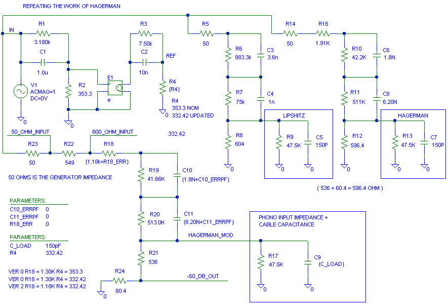
When I sent a pre-release of this page to Jim for comment**, Jim was nice enough to tell me that R4 in the schematic below is not 353.3 ohms (the value used in his article) but actually 332.42 ohms. It doesn't make too much of a difference in the audio band, but a mathematical reference is a reference that does not cost anything to have a few extra places accuracy.
I originally tweaked the circuit up with R4 = 353.3 ohms and came up
with R18 = 1.3K. With R4 equal to 332.42 ohms, R18 looks better at 1.18K
(A 12.7k across the 1.3K)
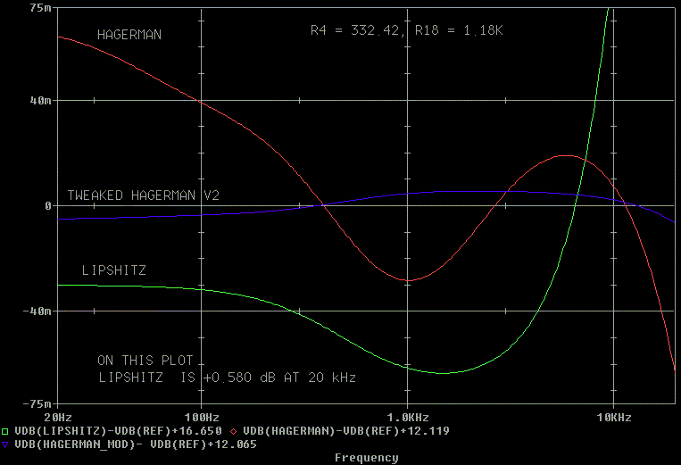
Here are the errors in dB of the three circuits versus the ideal response.
Hagerman's design actually is good to start with. As you will find out
in a minute or two, +/- 0.07 dB variation is nothing compared to what the
part value differences will do. In the graph below I changed R4 from 353.3
ohms to 332.42 per Jim's comments (thanks) and left R18 = 1.30K (what worked
best with 353 ohms). It is still not too bad.
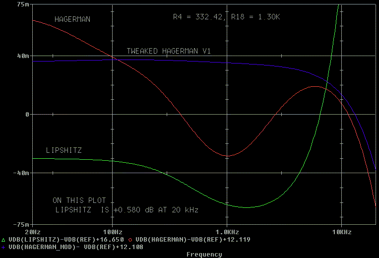
I played just a little with R18 and changed it from 1.3K to 1.18K and
got slightly better results.
Since we can measure resistors with an ohm meter, we can trim the resistor
values to be as accurate as we want or as accurate as our ohm meter.
I can get 41.66K by using a 51.1K in parallel with a 226K.
The 513K can be a 511K with a series 2K. (I used three resistors to
get 513K because I didn't have a 511K on hand.)
Since the resistors can be set much better than 1% manually, lets wiggle
the 1800 pF (C10) capacitor values between -5% and +5% in 1% steps (18
pF) and see what happens.
Note the change in scale from +/- 0.075 dB to +/- 0.400 dB. Look how
much more the capacitor variation is than the variation of the "ideal"
circuit (0%.)
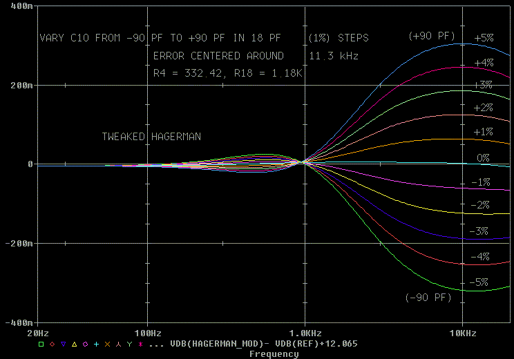
Now lets wiggle C11. Notice how C11 (6200 pF) changes the level everywhere.
C10 (1800 pF) changes mostly just at 11 kHz.

I don't see the point in trimming the capacitors. If you want to try,
here is what I'd do:
First start by setting the 170.6 Hz gain to be 3.373 times the DC output
level.
Then try to set the 11.22 kHz gain to be 52.458 times the DC output
level.
Measure the gain, convert to dB (20 log (V1/ V2)), look it up on the
chart and correct the value.
Note: The 20 Hz level is 1.0761 times the DC level.
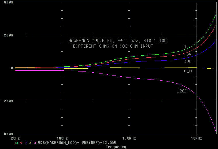
Now lets take a look at what happens if the input resistance from the
generator is wrong.
Boy, everything moves if we use a microscope and we hit the table with
a hammer. But we don't listen with a microscope.
First
edition 24-Dec-02, Last Update 7-Apr-2003
I
don't change the update date on individual sections for minor corrections.
I only change the date for content changes.