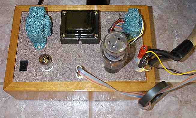
* The thin yellow and black wires are the inputs to the powered subwoofer.
* The fat cable is for the speaker.
* The toroid on the interconnect is a made of TDK H7C4. This common
mode choke helps remove some of the grain from the system. There are 4
turns on the interconnect, 3 are visible. Each pass through the center
hole is 1 turn. A Fair-rite toroid 5978003801 from Mouser should work just
as good. (12/30/00 picture of Stock Amp)
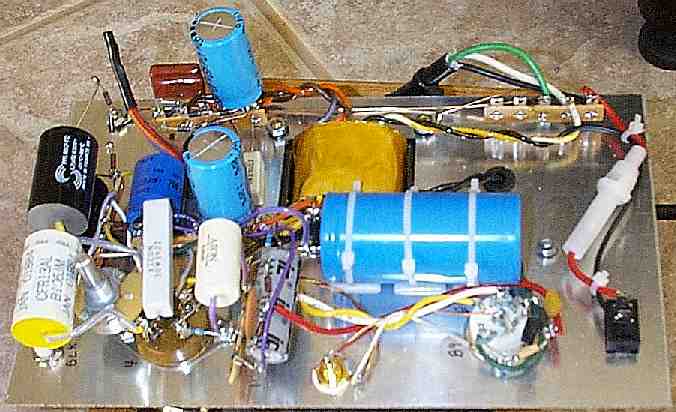
I really could not get a good clear picture with the camera I borrowed
this time.
There are three nylon cable posts holding the large 100 uF 500V capacitor
down. You can see the lossy Parafeed capacitor and resistors, the HV snubber,
the 2A3 filament bypass, and the extra filtering for the driver tube and
its filament. I cable tied the fuse wires because I was worried with all
the bending around it was seeing that the wire would break at one of the
solder joints (12/30/00).
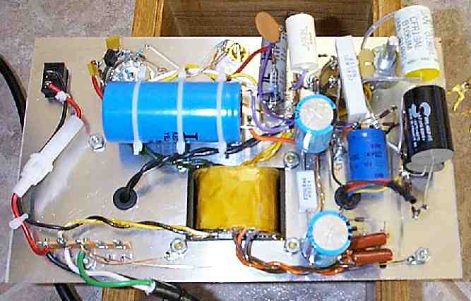
Below is a different view of the bottom (12/30/00). I'll shorten and tidy up the leads once I'm done playing around with parts as much as I current am doing. The top SCR (lossy Parafeed) capacitor will soon be RTV'd the SCR capacitor below it.
Link to Voltsecond's Paramour contruction notes.