I was having hiss and harsh sound issues with my bone stock Foreplay Preamp. It was still worth the $130 I had in it so far ($99 + $15 wood base + $16 paint and stain), but I wanted more. Greedy, aren't I. (Since I'm comparing it to a $1K preamp, Doc should be proud.)
When I hooked my oscilloscope on to the preamp output at 5 mV/ division, I could see a local AM radio station on the preamp's output signal and a millivolt or two of white noise. This was with none of the inputs plugged in and the volume controls set to 700 ohms to ground.
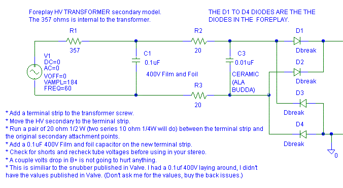
I installed a 0.1 uF snubber directly on the HV secondary and saw that peaks in the noise were reduced, but most of the white noise and the radio station were still there. Interestingly enough, the noise was much less on the grid of the cathode follower than on the cathode. This would indicate that a grid stop resistor may be called for, but I didn't want to try that yet.

Notes:
1. R1 (357 ohms) is internal to the transformer.
2. The very first snubber I used was just a 0.1 uF 400V film and foil across the HV secondary. (I used C1 only and none of the other parts.)
3. The next snubber I used is similar to the standard Valve Foreplay snubber, but not the same. I don't know which snubber is better. The valve snubber parts are available at Radio Shack, mine are not. (I used C1, R2 and R3.) With only one snubber capacitor and at low currents (<1% B+ drop because of adding R2 and R3), I prefer to have R2 and R3 between the diodes and the capacitor so they can help reduced the reverse recovery spike into heat faster.
4. Per a suggestion from Paul Joppa, I added C3. My original snubber only had C1. C3 is a Radio Shack 0.01 uF 2 kV. C3 is put right across the diodes of the diode bridge to try to get rid of that last tiny bit of repetitive noise on the output. The noise seen on the scope was a bit better with C3. Unfortunately, I didn't get to listen to it with the same piece of music soon enough to tell if there was a difference. Adding the 0.01 uF is technically the correct thing to do so I'll leave it in.
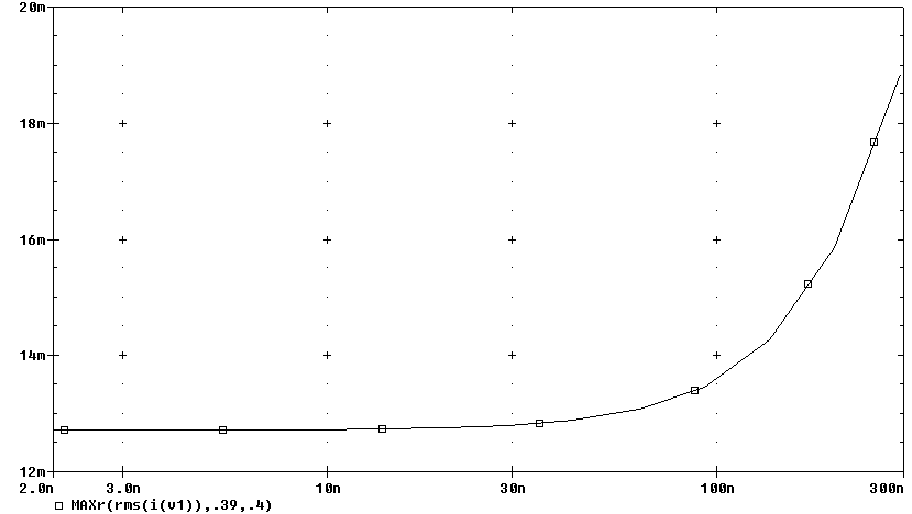
I modeled the snubber current in Pspice, any snubber much larger than 0.15 uF total capacitance starts to significantly increase the Foreplay transformer current. The Pspice model was more complex than the model shown above. The following chart shows the Foreplay HV transformer secondary RMS current versus the total snubber capacitance.
At 0.15 uF total snubber capacitance, the RMS current in the transformer is up about 12% which means the copper losses in the transformer are up 25%. My transformer was still reasonably cool to the touch after the mod, so I think we are OK with the added losses.
Since the noise was still there with the HV snubber, I went on the the next step: I snubbed the filament.
I removed the tubes from the sockets before I soldered on the sockets. I recommend that you do the same. I've gotten a tube stuck before with the flux that ran down the pin.
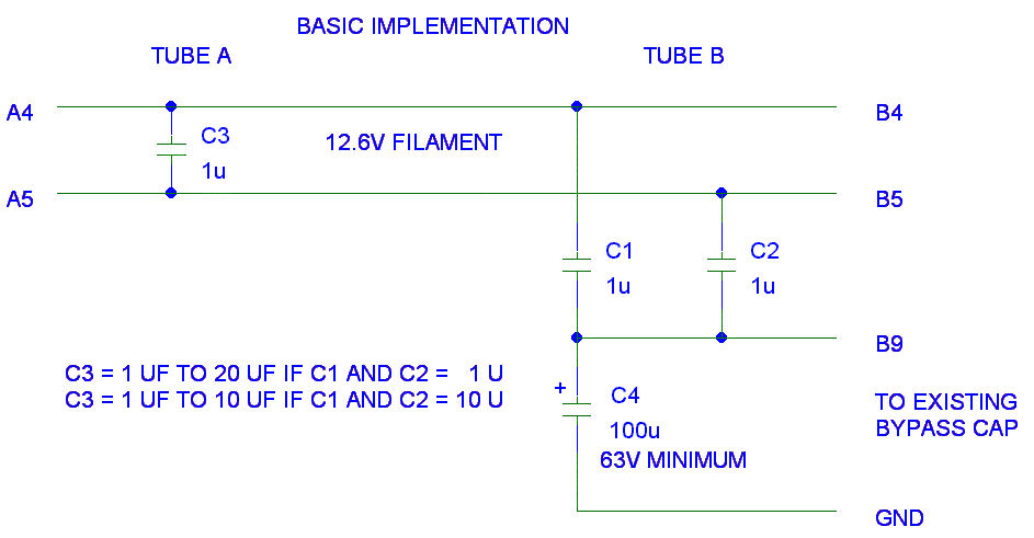
First I placed a 1 uF 50V X7R ceramic capacitor from each end of the filament to the existing 0.1 uF bypass cap on the tube's filament center tap. This was one cap pin B4 to pin B9 and one cap pin B5 to pin B9.Second, on the other tube socket, I place a 1 uF 50V X7R ceramic across the filament (pin A4 to pin A5).
I've done this modification before on my Dynaco MK IIIs, but that was before I had a scope and could see what was going on. On the MK IIIs I heard a reduction in the noise floor and an increase in the sound stage, so I had hopes this would work on the Foreplay.
After installing the filament snubber on my Foreplay, I plugged it in, applied power and the white noise and radio station were gone (at least at 5 mV/division). Now I all I saw was an ugly 60 Hz ripple on the output with an amplitude of a millivolt or two. I couldn't see this 60 Hz before because the radio station was hiding it. Just for kicks, I put a 100 uF aluminum capacitor across the existing 0.1 uF filament center tap (B9) to ground bypass capacitor. The 60 Hz was cut about in half, and now it was almost a pure sinewave. I used a 160V rated capacitor because it was in my junk box, a 63V capacitor is what I'd buy.
I checked all the solder joints and took the preamp back to the stereo.
What a change! The sound stage opened up. The hiss was only audible when
really close to the speakers and the harshness was gone. I didn't hear
any hum. This was the Foreplay sound everyone is so excited about.
It recently rained for the first time in months at my house (I live in the Arizona desert and it doesn't rain too often) and while I had the scope on the Foreplay, the "A tube" had that darn radio station back on it with much more amplitude than the "B tube" did. I had a couple 1 uFs left, so I did the Fancy Implementation of the Foreplay filament snubber. The radio station pick up was reduced. I thought I heard an reduction in the system's background noise too. (It could also be that awful proud poppa syndrome acting up again too.)
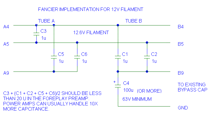
Bottlehead has changed the transformer in the Foreplay to have a 6.3V instead of a 12.6V filament. This is my recommendation for the new filament snubber:
First, you have to pull all existing B9 connections but the filament
power wire and label these "Existing Bypass CAP"
The "Existing Bypass CAP" will consist of two resistor leads
and a film capacitor lead.
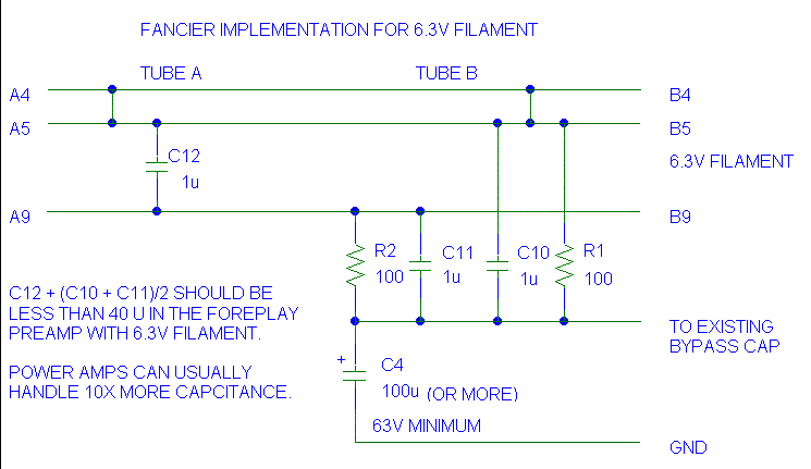
R1 and R2 balance the 6.3V around the center of the filament with the hope of reducing the 60 Hz coupling to the cathode. R1 and R2 are picked to conduct 5% to 10% of the total filament current.
2 filaments * 0.3A per filament = 0.6A,R1 and R2 should each be able to handle the full filament voltage so that if they are miswired, they don't go up in smoke. 6.3V^2/100 = 0.397W so R1 and R2 should be 1/2 W parts. In normal operation they dissipate (6.3V/2)^2/100 = 0.099W. If you really want, you could use 1/4W resistors for R1 and R2.
6.3V / (0.6A * 0.10 ) = 105 ohms total
6.3V/ (0.6A * .05) = 210 ohms total
C10 and C11 short any high frequency common mode noise down to both C4 and the original film cap (not shown) across C4. C4 shunts the low frequency common mode noise to ground. C4 should have it's own ground wire to the final power supply cap ground. Common mode noise is noise that appears in phase with the same amplitude on both B4 and B9 with respect to ground. (If B4 goes up 0.1V with respect to ground, so does B9.)
C12 doubles the effective capacitance across the filament and helps reduce differential noise on the filament (noise between B4 and B9.)
These numbers are valid for indirectly heated tubes only (12AU7, 12AT7 etc.) In a directly heated triode (DHT), the "100 ohm" resistors R1 and R2 each conduct 1/2 the plate current plus what ever flows from the filament. In a DHT, R1 and R2 are the legs of the hum balance pot.
I have not tried this on a DHT yet, however, I recommend installing C12 with a large nonpolar value and keeping C10 and C11 small. C12 is not directly in the audio path, C10 and C11 are. I recommend making C12 big, but limit the size so that the filament current only increases 10%.
With a 2.5V 2.5A filament:
Total RMS current = sqrt( resistive portion ^2 + capacitive portion ^2) => 2.5 * 1.1 = sqrt( 2.5 ^2 + Ic ^2)
Ic ^2 = (2.5 * 1.1)^2 - 2.5 ^2
Ic = sqrt( (2.5 * 1.1)^2 - 2.5 ^2 ) = 1.15 amps in the C12 capacitor
at 60 Hz
Note: the filament is 2.5V/2.5 A = 1 ohm
Xc = 2.5V/ 1.15 amps = 2.18 ohm Xc = 1/(2
* pi * f * C) C = 1/(2 * pi * f * Xc)
C = 1/(2 * pi * 60 * 2.18) = 1216 uF maximum nonpolar!
Just for kicks, lets calculate the 3 dB point with this cap and our
1 ohm filament:
f = 1/(2 * pi * 1 ohms * 1216 uF) = 131 Hz. That's a lot of filtering.
I'd probably use a 100 uF Mylar (TM) film bypassed with a 1 uF ceramic for cost and size reasons. Keep in mind that the C12 capacitor will be radiating filament noise so again: There ain't no such thing as a free lunch! (TANSTAAFL) I'll let every one know this works once my Paramour is done and the mods begin.
I have posted on the Bottlehead forum that a large the output capacitor on the Foreplay output will help with rejecting low frequency noise but the larger capacitor will have more surface area and volume to pick up electrical noise. The larger cap insures that the output impedance of the Foreplay cathode follower is the limiting factor in adsorbing noise coupled to the cables attached to the Foreplay output. I experienced this hum reduction when I changed my output capacitor from 2 uF to 4.7 uF.
Unfortunately, someone just experienced noise pick up from the output capacitor. On 3 Nov. 2000 Miguel posted on the Bottlehead forum that he shielded his output capacitors to kill a radio station on his Foreplay's output. Unfortunately my filament snubber didn't work good enough for him for fixing his RF problem.
Here's the link to Miguel's
shielding the FOREPLAY output capacitor post.
*** I got my 1 uF 50V X7R capacitors (the value is marked 105) at the local electronics recycling yard. The caps are old military surplus capacitors. I had to scrape the leads with a Scotch-Brite (tm) and pre-tin the leads with Kester 44/RMA flux to get them to take solder. You can buy new ones from Newark, but they are about $1.40 each in low quantities. If you buy thousands, you can get a much better price.
I like the molded X7R capacitors better than the dipped ones. The leads on the dipped ones occasionally fall off if you don't use a solder heatsink on them when you solder them. The dipped X7R ceramics are available from Digikey. The X7R capacitors are small for a 1 uF capacitor. Because they are small, they are both less likely to pick up electrical noise and they are less likely to radiate filament noise into nearby parts.
*** Many people are having good luck with this mod using 1 uF Z5U capacitors. These are much much less expensive than the 1 uF X7R capacitors. You can't argue with success, even if the X7R is a better part.
*** WHAT! I'M PUTTING CERAMICS IN THE PREAMP! Don't worry, these capacitors should not be in the signal path at all. They are installed to kill power supply noise and filament induced noise pickup. The X7Rs work well in this location. Some may argue that if the sound is affected by a part placed anywhere in the circuit, that part is in the audio signal path. I don't want to operate that way. If I do operate that way, I have to start worrying about what is in my neighbor's TV set because he connects to the same electrical grid that I do.
Avoid metalized polyester for this application. I tried them once in a similar circuit and they did not work. Polyester film and foil should work, but will be harder to install than the small X7R caps. The capacitor from A4 to A5 on the 12.6V version (A5 to A9 on the 6.3V version) may benefit if it is made larger. I suspect that you can go up to 20 uF and not over stress the 12.6V transformer filament winding. You'll have sqrt( 0.3A^2 + [13 V * 2 * pi * 60 Hz * 20uF ] ^2) = 0.316 A RMS not 0.300 A RMS on the transformer filament winding.
Not all metalized capacitors are to be avoided in this circuit. If the
capacitor is rated for high ripple current or pulse discharge service,
it may work. Just because a capacitor says it is for EMI filtering/line
bypass, does it mean that the capacitor will work good enough. The problem
with the large films is that the case of the part radiates noise when they
are attached to the filament. Keep them away from the grid of the input
tube.
From what I've experienced so far, it appears that both the HV and the filament transformer connections need snubbing/capacitor bypass. If you put DC on the filament, it should still benefit from snubbing the transformer winding and from bypass capacitors to ground.
First release about July 2000, Last update 6 Nov. 2000, Worked on grammar a bit 1 Apr 01.