Preface
“A door has opened for you, and your family, on virtually unlimited years of musical enjoyment.”
Avery Fisher, 1964g.
If you like tube sound, vintage Fisher tuners/amplifiers are among the top choice – they are well designed and build, and despite 40+ years of age, still provide many people with the excellent and enjoyable listening experience. If you purchase it you will not regret – generations of music lovers cannot be wrong!
However, after 40+ years of usage, just like any other device in this world, they require service maintenance. You may purchase a serviced unit (usually $600 – $900), or, if you are fluent in electronics, obtain a virgin amplifier, and restore it for yourself. This article is for self-servicing tube junkies. It is mostly devoted to Fisher 400, second tube gear I had. Anyway, generic details are the same for all devices with similar assembly (Fisher 500, 800, etc.).
Purchasing Vintage Tube Equipment – Golden Rules
- The unit must be in working condition. If it doesn’t work, you never know for sure why. It is not a problem to replace a burned-out vacuum tube or cap, but it is very difficult to find new audio or power transformer. In fact, smoked transformer means acquired gear will be only good as a donor unit for spare parts.
- The visual/cosmetic condition must be 7+ by 10-grade scale. Faceplate with deep, clearly visible scratches looks just ugly.
- There should be no rust on the chassis, audio, or power transformers. If the amplifier was kept for a decade in a dirty and wet warehouse, its a junk.
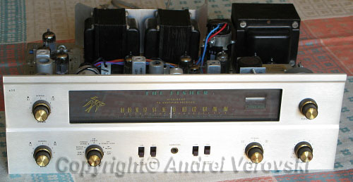
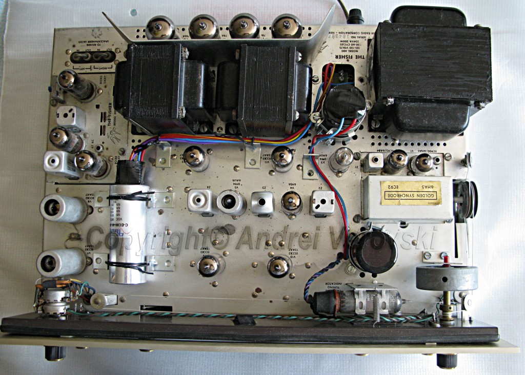
As you can see, despite 44+ years of age at the moment of purchase, there are very few noticeable signs of wear. The only noticeable problem was a power supply filter capacitor with a small but visible level of the leak.
 Before You Start
The power rails of vacuum tube amplifiers are 400v+. It’s a lethal voltage, so make sure you know what you are doing. I will not describe which instruments you should have – if you are fluent in electronics you know for yourself, if not, just don’t do it. Of course, the service manual and schematic diagram is a vital piece of information. You can download Fisher 400 service manuals version 1 (sn# from 20000) and version 2 (sn# 20001 to 29999). At the time of restoration, I had the only the first one, and it was really a nasty surprise for me to discover that my unit was slightly different modification (one vacuum tube less, few capacitors with different values, etc.). That’s turned the restoration process into an unforgettable venture, or hell, name this just you like it. Later you understand why.
First Steps
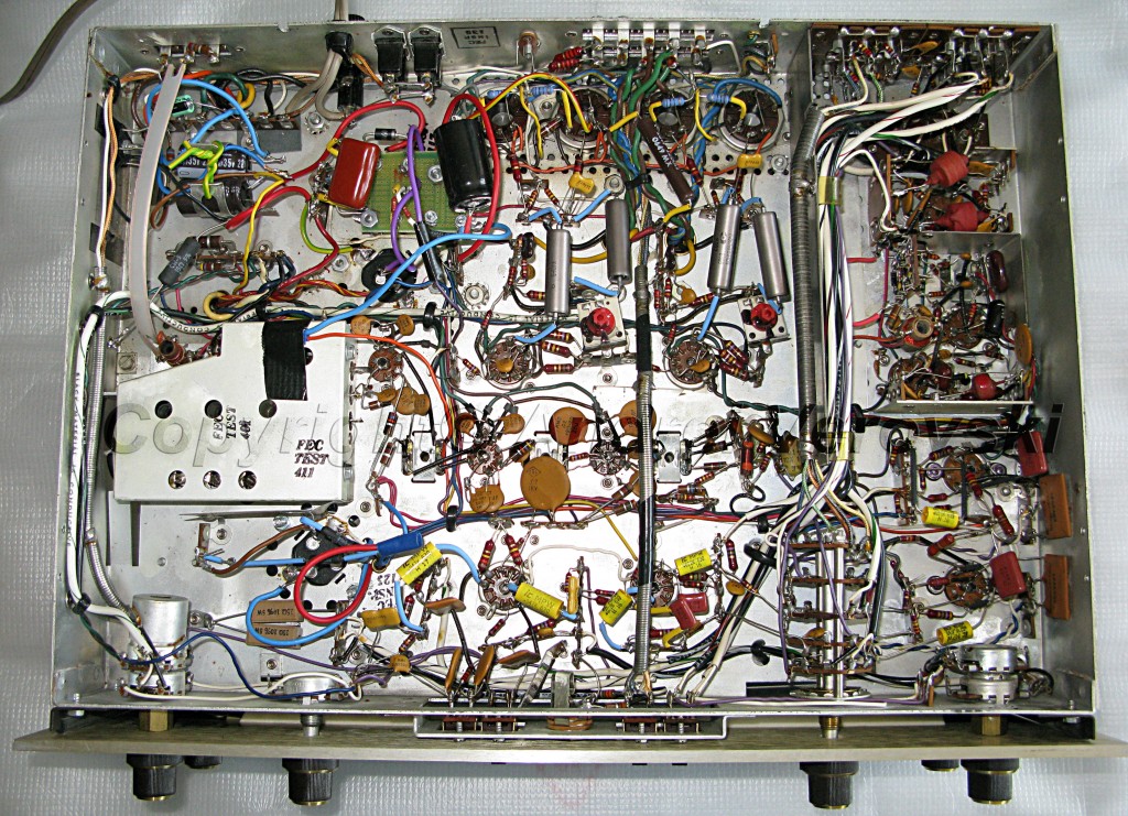
After the visual inspection, you should make close-up, high-resolution photos (with 9 – 12 mega-pixel digital camera) of the circuit. Fisher, like many other tube amplifiers, used point to point circuit, and not PCB (printed circuit board) or large soldering terminals. If you remove several components at once, it is absolutely vital to install new ones in correct places. Believe me, it is not very easy to navigate in a crammed jungle-like place with a lot of cables, resistors, etc.
Without a hi-res, high-quality photos it is simply impossible to have a clear picture like this one. Please pay attention to how clearly visible are all elements, including cables. One more thing – if electrolytic capacitors are leaking, try to clean all remaining liquid.
How to open hi-res images. First, click on the image or link. A new window or tab (depending upon browser/settings) will appear. Then, click on the large thumbnail, and you will see full-size image. Take into account, however, they are quite large, up to 4000×3000 pixels, and may take time to download.
Components
These components must be replaced:
- for safety reason – selenium rectifier, old power supply diodes, electrolytic can capacitors, and resistors + 4 new 10 Ohm cathode resistors.
- for obtaining the highest-quality sound – coupling capacitors.
- if you plan to connect turntable – coupling capacitors and resistors in the phono section.
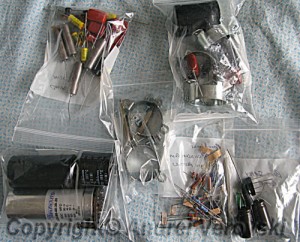
Since I have not restored tube amplifiers before, I used a step-by-step approach: replace/upgrade something (e.g. bias supply) – see how it works. Spare parts may be purchased from any source, but I obtained them all at once from Jim McShane – a really excellent expert in vacuum tube gears. There is one, absolutely vital issue with restoration spare parts – they must not only be of proper values/technologies, but they must physically fit into the cramped space. I have seen other Fisher restoration kits, but they do not include large can caps, and therefore, are only partially useful. In fact, proper can caps are the biggest issue in the whole process.
On the picture, clockwise from top-left: coupling caps, power supply parts, bias parts, misc caps and resistors, large electrolytic caps, in the middle – stacking hardware.
Upgrading BIAS
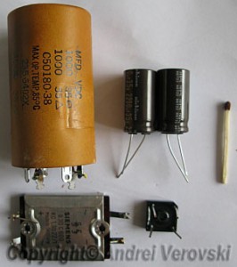
I recommend to start by replacing parts in BIAS circuit: selenium rectifier, filter caps/resistors, and installing 4 pcs of 10 Ohm protection resistors (between 7868/7591 cathodes and ground) to ensure audio transformers will not be burned even if the output tube circuit will be shortened.
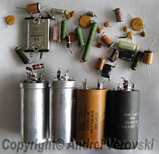
As you can see, the new components (right) are much smaller than then old ones. Left – 2 section C60A/B 2×1000 mkF 35V (top) and selenium rectifier (bottom). Right – 2 x Nichicon caps 2200 mkF 35V, diode bridge. Not all bias parts shown on the picture! One of the small caps (C42 100 mkF 25V is quite hard to install because of cable over the top of the soldering terminal). After you finish work, turn on the amplifier to ensure everything works correctly.
Power Supply Upgrade
First of all, you must remove large multisection can caps.
Some of them are not mounted using clamps/screws/rivets but soldered directly to the chassis with 4 aluminum pins. They are really hard to get rid of. Since they were made with aluminum, which is relatively soft and weak metal, and soldered to a thick steel plate, I used brute force to break aluminum connectors. However, this is a very tricky procedure, you may easily scratch or damage virtually anything around, so try to use a soldering iron. Additionally, you will need to remove several rivets. Unlike screws, they are “drilled through” with 4 mm drill until they fall apart.
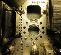
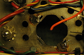
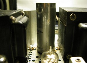
And now the problem which almost drove me mad. The rectangular hole (left image on top) made virtually impossible to properly mount a large 4-section can cap (C52). It is supposed to be screwed on using two distancers and a small plate from the bottom side of the chassis. Of course, it was not a big problem to mount it on the top, but then, it appears too high.
 |
 |
| Can Cap Installation Place | |
 |
|
Due to the extra height of the can cap, it is now not possible to install Fisher in the wooden cabinet. Probably Jim had Fishers with a round hole instead of a rectangular one. One more caveat – all can cap connectors were used as mounting/soldering points. If the cap is moved elsewhere, there are no more points to solder resistors and diodes, they cannot just hang in the air.
So I have decided to assemble a small circuit board and install it vertically right over f*** rectangular hole with 2 angled metal corners. For 4-section can cap, I found a good place to mount it horizontally (I’ll show it later). I have verified the amplifier with all that stuff, worked great, and now it was a time to screw on this board. Oops! Board could be perfectly fit if there are no so many thick, high-voltage cables attached! They touched the metal screen of the output tubes section, which, after a certain time, becomes very hot, and could melt the wire’s insulation. At first, I am was thinking to put heat insulation between the metal plate and cables, but abandoned this idea, it would be too awkward.
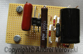 |
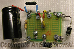 |
|
Old Board |
New Board |
A new power supply circuit was quickly build using a smaller self-made soldering terminal. Power cables connectors are on the side instead of the bottom. I mounted it using two distancers where one of the can caps was.
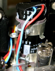 |
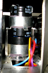 |
| C56 mounts on the chassis, and C57C above it with 2 clamps and distancers (with parts from Jim McShane) | |
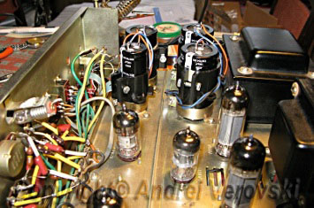
Stacking (suggested by Jim McShane) allowed substituting hard to find multi section caps with 2 general-purpose and affordable ones. However, during the restoration of my next tube gear, Pioneer SM-83, I found a much simpler and less cumbersome way of stacking using just one nylon clamp. The pictures are shown below.
 |
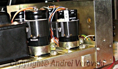 |
Additional to simplicity, stacking with nylon clamps has one important advantage – they are relatively soft compared to metal, and therefore, much less likely to damage thin aluminum cans of electrolytic caps. Warning: after finishing all work, top of the caps must be insulated
4 metal corners (glued with Bison construction adhesive) were used to mount 4-section can cap C52 horizontally on the chassis as shown in this picture. Another 3 corners help to direct wires in a safe way (pass around vacuum tubes without touching them).
Do not forget to shield can cap connectors with insulation, otherwise incautious move may lead to lethal 300 – 500v charge. Check everything again after you have done this, any wrong connection may lead to the total amplifier annihilation. 500v voltage is not a joke!
Replacing Coupling Caps
Old ceramic/mica caps are replaced with new ones (mica, metalized polypropylene, paper in oil) with low ESR (Equivalent Series Resistance) value. I did not change resistors in Phono section, my turntable was lost in transit from Germany and I decided not to join the vinyl club. As I mentioned before, the point to point circuit is very cramped, and some small caps are hard to remove even with small tweezers because they are soldered between other components and chassis. PEC (packaged electronic circuit) modules used in bass/treble control and few other places also very desirable candidates for the trash can, but it is not so easy to replace 5×5 mm part with several discrete resistors and capacitors, there simply no mounting points for them.
This how the circuit should look after restoration process is complete. On the top left of the circuit – new supply circuit board.
My restoration process was finished successfully, without burning or damaging anything. The amplifier runs very hot – one can notice a stream of warm air over the power tubes and audio transformers. My output tubes Sylvania 7868 produced hardly noticeable (visible only in dar room) blue light (along with orange light from the cathode heater). Members of Audiokarma forum told me that this is rather normal, and should not be a source of any doubt.
Using New Production Output Tubes
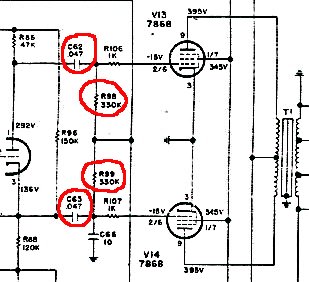 If you plan to use new production tubes (Electro-Harmonix, Sovtek, etc.) instead of NOS (New Old Stock, manufactured back in 50s – 60s, like RCA, Sylvanie, Telefunken), you will need to make a small adjustment in the output stage to make it work stable with new tubes. Look at the schematic diagram on the left. There are 2 x 330k grid leak resistors (sets the impedance of the stage and biasing) and 2 x 0.047 ukF coupling capacitors which need to be replaced with 180k – 220k and 0.1 – 0.22 ukF respectively. Since there is always residual gas remaining in the tube, a side effect called gas (ion) current occurs. Under certain circumstances, high value of grid leak resistors may raise anode current, turn this process into a self-sustained mode, and eventually overheat the tube.
Aligning
I am was lucky enough to get an amplifier with all vintage tubes (RCA, Sylvania) in good shape. First of all, you need to check idle current (with volume control at zero) over power tubes (35 mA max). Therefore, the voltage on 10 Ohm cathode protection resistors must be around 320 – 350 mV, it should very close on each pair (thus, you can really check how your matched pairs are really matched). Additionally, I have checked the voltage on all pins and found a very strange issue. Everything was fine except grid voltage on 7868 output tubes pins# 2/6, on the schematic diagram it was 15V, mine was 10v. Strangely enough, the idle current was OK and the amplifier sounded absolutely nice. As suggested Tom Bavis from Audiokarma, my voltmeter with low input resistance might be a culprit. And it really is, how I could oversee that?
Last Word
Since output power of most vintage vacuum tube amplifiers is only 2 x 25W – 30W, speakers with high sensitivity (95 and over) dB/W/m are mandatory to obtain sound volume enough for average living room without clipping and distortion. I have a pair of such – Technics SB-G710 and Sansui SP-Z99. Both are 4-way with huge woofer and 98/100 dB/W/m sensitivity respectively.
PS.
At the end of 2008 I am bough a second tube amplifier – Pioneer SM-83. My collection of vintage gears grew rather big and space consuming, so I have decided to sell all stuff I do not use daily – several solid-state Sansui gears, hybrid Fatman amplifier, extra speakers which have collected dust, and this Fisher standing in the bedroom. After all, Fisher found a new home in UK. This is what Bruce H wrote me a month later: “I’ve been listening to the Fisher most of the day and it’s been sheer joy… Anyway, just wanted to tell you how pleased I am with the Fisher. You did a very good job with it. It sounds fantastic.”. Thanks, Bruce, I am really glad when people enjoy my work. In the meanwhile, I have continued my SM-83 restoration…
Q&A
Your questions and feedback are always welcome. Please feel free to contact me, I will post most interesting Q&A material on this page.
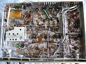
Leave a Reply
You must be logged in to post a comment.