SEUL 22W MONO BLOC 13E1
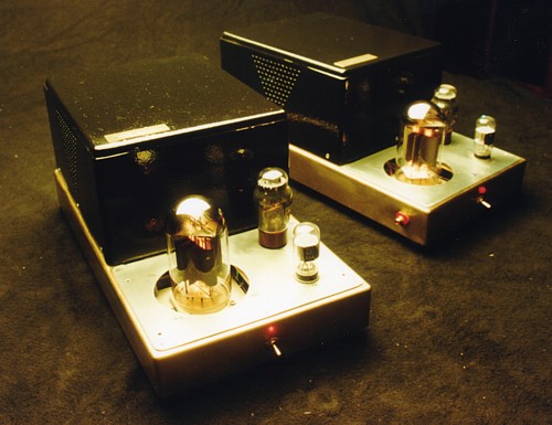
Fig 1. SEUL 22W mono bloc with 13E1.
Edited in June 2012........
The two mono blocs shown were built in 1997 to prove nobody needed
to spend an absurd amount of
money to achieve the best sound from a Single Ended design. Some
audiophiles said these amps have a
midrange you would die for, but also said the bass and treble was
remarkable, and better than many might
expect from an SE amp. The 20W full power response is from 20 Hz
to 65 kHz. They give 22W for 8r0
and 27W for 4r0. There is enough power for most listeners with
normal modern speakers of typical
sensitivity of 90dB/W at one meter.
The amps used the rugged 13E1 beam power tetrode which probably
stopped being made in the late
1960s. This tube was fashionable among the hi-fi cognoscenti and
magazine paparazzi of the Hi-Fi media
because it is a beam tetrode, and not a triode. But within the
Hi-Fi media, few people have any technical
skill or knowledge, they compose meaningless words and perpetuate
irrational prejudices. They regularly
give good reviews of some ridiculously expensive junk submitted to
them for appraisal for which the junk
maker pays a high price.
This situation is good, because the stocks of the 13E1 tubes will
last longer and prices will remain lower
if people are snobbish enough to ignore what is a very nice tube.
I would not want to see hoarders and sharks buy up stocks of such
tubes because they become both popular
and rare, and end up under someone's bed gathering dust for 40
years!
I first bought a pair of these tubes in 1996 without knowing what
I would do with them. I explored their
capabilities for SE triode and Ultralinear operation by connecting
the screen to various taps on an SE OPT.
In pure tetrode, regardless of Eg2, value the tube is not very
linear and generates a large array of even and
odd harmonics even at low Po. But this is to be expected with many
beam tetrodes and pentodes which may
make 14% THD just before clipping. So I did not find it very
suitable for pure SE tetrode with a fixed screen
voltage. But when the screen is connected to the anode to make the
tube work like a triode the linearity is no
worse than many other large genuine triodes.
It has a very low triode Ra of only 300ohms, and it will generate
a very sounding nice 16W into 1k5 anode
load. I found the best tap for UL was at 66% of anode winding for
the screen to get a negligible increase in
the complexity of THD spectra compared to triode, where the THD
consisted almost entirely of 2H. 33% UL
taps gave spectra too similar to tetrode. The 66% UL tap allowed
max Po of 27W instead of only 16W
with triode. But Ra with 66% UL is 600 ohms, and some global NFB
was essential to keep the output resistance
of the amp low for a good damping factor.
Unlike most transmitting tubes such as the 845 and 211, the 13E1
does not require a +1,000Vdc supply.
13E1 were designed to work with anode B+ between +200V and +800V
with a screen supply low as +150V.
These low voltages allow the use of an indirectly heated cathode
as in 6550 or KT88 etc. In fact 13E1 has two
cathodes, not just one, to allow a massive peak current ability of
about 800mA. Some people have told me they
have used a few 13E1 for an OTL amp! Although a pair can make 200W
in class AB tetrode, I wanted to make
an SE amp so efficiency limits the pure class A output to about a
maximum of 40% of the safe working maximum
of plate Idle Pda = 72W.
The tube data suggests max Pda = 90W, but this is a design figure
for combined dc and ac Pda in class AB
push-pull amps where the ac duty cycle is never continuous as it
is with pure class A. I got a maximum power
output of around 27W for SEUL operation, so the anode efficiency
was 37%. If 13E1 is set up with idle
Pda = 90W, the anode will glow dull red and the sound will be
quite dreadful and the tubes will not last long.
The 13E1 I purchased in 1996 lasted well until 2006 with use
exceeding many thousands of hours.
Although there is some slight reverse grid current they are
serviceable and produced the same power and
distortion before the owner replaced them as a precaution. The
13E1 has a similar power output to a 211 or
845 transmitting tube, and the same excellent sonic
characteristics if set up just right. The selected drive tube
in 1997 was ECC32 and input was 12SL7, both with their two triodes
paralleled. In 2006, the driver tube
is a 6V6 in triode and 6SL7 at input.
The 6V6 driver tube gives slightly less thd, but allows the use of
much lower bias resistors for the output tubes
to prevent slight DC bias drift after 8 years of constant use. The
amp was constructed so that if no 13E1 are
available in future. 4 x EL34 or 3 x 6550 or KT88 or KT90 or KT120
could be used instead in SEUL or
triode mode.
The tubes are mounted on a sub-chassis which could be unscrewed
and replaced by a new chassis for
different tubes. The power supply has several taps for different
HT. In 2012 I found NOS 13E1 are not too
hard to source, and the owner of these amps got a spare pair for
the future. Chassis is brass plus aluminum
and the enclosure right around the power supply is painted mild
steel. Size is 470 long x 240 wide x 220 high
and weight is about 25 Kgs. A perforated steel cover was supplied,
and which screws down over the tubes,
but is not shown.
These amps were used with pairs of my speakers at a March
2001 meeting of the Audiophile Society of
N.S.W. aka ( ASON ), giving excellent sound for a large room with
30 listeners.
Please excuse the hand drawn schematic from 1997, well before I
knew how to use a PC......
Fig 2. Schematic SE25 with 13E1.
Fig 2 schematic is fairly basic but a few items need careful
attention should anyone wish to build a sample of
this amplifier. Where possible star earthing and good wiring
practice should be used with point to point on
tag strips. The stability of any tube amplifier including this one
will depend on the quality of the output transformer.
I usually wind all my own OPTs because custom winders cannot be
relied upon to wind the OPT how I like
them to be wound, if ever anyone to can be found to wind OPT. But
the OPT should have Lp > 15H, LL
< 5mH, and total Rw < 7%, and Cshunt at anode connection
< 1,000 pF. Primary load is 1k7 center value.
This basic specification has always been difficult to find
anywhere. With the above specs the the circuit needs
to have some tweaking of the open loop gain and phase shift
character so that when global NFB is applied it
is impossible for the amp to ever oscillate regardless of whether
there is a load connected or not, or whether
the load is any value if L or C.
R & C values of the following components must be selected and
checked for correct maximum stability margins :-
R6+C5, low F phase shift reduction; values shown should suit most
OPTs.
R33+C27, high F phase shift and gain reduction; they need to be
carefully trimmed.
R20+C14, high F phase advance network for voltage NFB; must be
trimmed.
R19+C12, high F zobel damping network to stop parasitic
oscillations at RF.
R21+C15 high F zobel damping network to provide a load at above
100kHz.
All the R+C values mentioned are fairly critical and cannot be
assumed to the same as my schematic because
your OPT will have
different Lp, LL, and shunt C compared to what I wound myself.
The schematic shows a speaker can be plugged in between COM and
VFB or CFB. Using COM to VFB,
there is only ordinary conventional Global NFB, or series Voltage
negative feedback. This connection gives
lowest Rout, and suits all dynamic speakers.
If speaker is between COM and CFB, there is added Current negative
feedback.
The added current FB gives slightly higher Rout up to 1r0, but
better control at HF for electrostatic speakers.
When COM to VFB is used virtually no current flows in R22 0r1 and
the zobel network of C15 50n and
R21 8r2 act normally to give a resistance load to OPT sec above
300kHz to ensure RF stability.
But if the COM to CFB is used, all speaker current flows in R22
0r1, and if there a low RL due to C load
the current in R22 adds to GNFB fed to input triode cathode and I
found this gave less overshoot or ringing
with square waves. Feedback application is not easy to
understand, and I make no apologies for confusing
people if I appear to over simplify what is involved.
You are welcome to do their own analysis.
Most people select the COM to VFB speaker connection as being the
one that sounds best, and nobody
used ESL. In later modifications to this amp, I didn't bother
keeping the two types of NFB; it was better to
just stay with simple GNFB only, and give more attention to its
optimization.
NFB isn't evil unless it is abused by ignorant designers or
wannabe DIY amp experts.
Fig 3. One SE25 on bench, covers off.
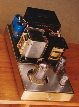
The PSU cover is removed, showing C-core output transformer, large
choke, caps,
and large power supply transformer at the top right rear.
Fig 4. Distortion Graphs.....
The above graphs look quite strange compared to typical curves
published in 1960 which used
LINEAR scales for THD% and Vo.
This made the graphs look better, and less alarming.
But I have used a LOGARITHMIC scale for the THD quantities so that
the amount of THD at
low levels is very easy to see.
Most buyers thought that all distortion is bad, and it is, but
depending on harmonic spectral content,
the perceived "badness" varies. Common average listening power
levels might be less than 0.3W, but my
graphs show 1W, 2W, 8W and 22W clearly. The UL mode gives THD 0.5%
without FB at 1W, and 15dB FB
reduces this to 0.12%. The THD is all 2H, and the sonic quality of
SEUL was found to be fine.
The Curve C shows a PP triode amp using say 2 x 6550 set up for
similar power and NFB. At the same
1W, THD = 0.02%, but it is mostly 3H. The measured distortion
should be "weighted" as H number rises
because the 0.12% of 3H sounds worse than 0.12% of 2H, and 0.12%
of 5H is worse than 0.12% of 4H,
and so on. To weight THD, apply the formula, Weighting Factor = H
number squared / 4, so then for
increasing H we get :-
2H, WF = x 1.0
3H, x 2.25
4H, x 4.0
5H, x 6.25
6H, x 9.0
7H, x 12.3
8H, x 16.0
9H, x 20.3
So the SEUL amp which has 0.12% of 2H needs no WF applied. The PP
amp with 0.02% 3H is equivalent
to 2H = 0.02% x 3 x 3 / 4 = 0.045% Clearly the PP amp measures
better, but the difference between 0.12%
and 0.045% is not huge. THD is NOT the actual problem, and is
merely a way of indicating a more difficult
to measure intermodulation distortion, IMD. It so happens that
listeners with above average hearing can
detect distortion in a sound system if THD is 2H and rises above
0.5% if the system has full bandwidth.
That was the view mentioned in RDH4, a fine text book of 1955.
What told listeners that distortion was
present may have been the IMD. To many people, IMD occurring in an
amp which produces THD of mainly
2H is much less bad sounding than that caused by THD of mainly 3H.
In the case of the SEUL amp, if music is played with or without
NFB applied, and AVERAGE levels are
kept at say 0.5W for either NFB condition, few people would notice
any difference, and if there was any
difference it could be due to the change in damping factor. The
use of NFB reduces amplifier output resistance
to less than 1r0, thus raising damping factor to be over 4 in a
worst case where a 4r0 speaker is used.
DF = Speaker impedance / Amplifier output resistance. The NFB
usually always makes bass sound tighter
and less boomy or wooly, and most people hear a general
improvement especially at high levels.
I am considering the case where the amp has adequate power to give
deafening levels of sound before
distortion becomes intolerable. If one were to use a single EL84
with maximum power of 5W, then at 1W
the THD will be much higher than that of a 13E1 at 1W.
With speakers rated for 90dB/W/M, 1W average level for 2 speakers
of a stereo system produces an SPL
of about 91dB. Most people think an average SPL level of 85dB is
quite loud enough, with peaks rising
perhaps to 100dB. To achieve the 85dB average level, power from
each amp is approximately 0.33W,
which is 1.62 Vrms into 8 ohms, and where THD < 0.06%.
Such levels of THD and resulting IMD in tube amps are negligible,
and cause zero distress with all listeners
I have known. Music has a myriad of harmonics with relate
mathematically and several different frequencies
played together sound pleasing in melody and chords. THD
production does not change the sound by itself
very much. But where IMD is produced, the sound can be changed,
and always made worse.
Suppose there are two signals produced with say 4 Vrms of 80Hz and
1Vrms of 1kHz, and there is harmonic
distortion, then the 1kHz level will be amplitude modulated. This
is the equivalent of having both tones present
but with additional tones of 920Hz and 1,080Hz. These added IMD
tones, or notes, are not nicely related
harmonically to other notes in the music.
Exactly what IMD levels are is able to be calculated, but there is
little space to devote to that now.
But with many musical tones present, there is a huge number of
"intermodulation products" and if they could
be played in speakers without the wanted non-distorted signal
present, the sound is like a rustling noise rising
and falling in time with the music.
Many people find the general clarity of music using a good SE amp
is often better than a PP amp with less THD,
and less IMD, so there can be a contradictory co-relation between
measurement and subjective assessment.
But I always try to minimize THD and thus minimize IMD, but
without making the amplifier too complex or
over-engineered.
People who favor SE amps usually say the SE amp will better
reproduce the natural recorded midrange
warmth without any loss of detail and precision in the dynamics.
But I have heard too many good sounding
push pull amps to agree which is generally better.
I am at a loss to explain all the opinions I hear.
Fig 5. SEUL Vs SE CFB.
The above graph has a log scales for both THD% and Output Voltage,
Vo.
There are two other scales below the graph for Output Power and dB
SPL. For example, where
VO = 2.24Vrms, Power from each amp = 1W. 2 speakers each producing
90dB SPL give 93dB
in an anechoic chamber at 1M. But in an average room at 3M, the
SPL may be 90dB at 3M with
2 speakers. You will find that for average levels of 87dB the
average Po from each amp = 0.5W, and
for 84dB, 0.25W. The graphs show THD from the SE35 amps with local
cathode feedback windings
( CFB ) is about 1/5 of that of the SEUL with 13E1.
The SE35 and SEUL have been set up with approximately the same
total amount of NFB. In years
between 2003 and 2007 I had two customers to whom I had sold
samples of both amplifiers and they
both listen to each others amps during friendly house visits and
they had a difficult time deciding which
was the better sounding amplifier. The owner of the SE35 sold it
to fund yet another amplifier purchase
because he seemed addicted to regular amplifier changes. One
cannot expect anyone to keep going to
see the same movie, drink wine from the same vineyard, or decorate
the house with paintings from the
same artist, or remain married to the same wife forever.
But I was pleased that his ownership of the SE35 was the longest
time he'd ever kept a good piece
of audio gear. The fellow with the SEUL snapped it up when it came
up for for sale. He eventually
decided the SE35 was a better amp than his SEUL25. Some
considerable modifications were done
to the SEUL to convert it to the SE32 at monobloc-se32-13e1-cfb-2012version.html
The performance of both SE35 and SE32 are now very similar, maybe
because both have very similar
overall design with triode input and
driver stages. The output tubes are both multigrid types and both
have local cathode feedback. SE35
THD figures are described in much more detail in the page devoted
to the SE35CFB amplifiers.
se35cfb-monobloc.html
THD in the SE35 is least when RL = 5r0, with THD being higher when
RL
is a value either below or above 5 ohms. THD cancelling between
the driver stage and CFB output
stage is most effective at 5r0. The result of the work with SE35
with CFB led me to conclude that I
should use part of the primary winding on SEUL OPT as a tertiary
winding for local CFB.
But my customer who owned both SE35 and SEUL thinks they do sound
similarly stunning. And to those
who still doubt NFB does any good in SE amps, let me say that each
and every triode already has a local
NFB loop within itself. It occurs because of the electrostatic
effect of the anode voltage upon the flow of
electrons to the anode. The control grid voltage changes the
electrostatic field between itself and the cathode,
thus controlling electron flow. So for a positive going voltage at
the grid, there is an increase in Ia. But as Ia
increases, the load voltage across the load between B+ and anode
increases, thus making the anode voltage
move negatively. The tube is an inverting amplifier. Now the anode
voltage swing is usually much larger than the
grid voltage swing. This anode voltage change also affects the
electron flow from the cathode. So as the anode
voltage falls, it tends to lessen the flow of electrons attracted
to itself. In other words, the anode voltage
change opposes what the grid is trying to do. The two
electrostatic fields sum together to give a resultant
field that works on electrons in the Ia flow. This is a form of
local shunt feedback, equivalent to having a
shunt resistance network of two resistors between anode and the
signal input, with the join of the resistors
going to the grid. ( I use such local resistance FB networks in my
preamps. )
The internal electrostatic FB in the triode is almost entirely
prevented by the addition of the screen grid as
used in pentodes and beam tetrodes. The screen usually has a fixed
voltage relative to the cathode to enable
pentodes and tetrodes to have very high useful gain and much more
output power than a triode with a similar
Pda rating. The price for this extra "free" gain and power is much
higher Ra giving a very poor damping factor
and a whole lot more harmonics, mainly odd numbered, and changing
in relative mix and phase with load c
hanges.
The screen affects the Ia flow in the same manner as it would if
it was an anode. So when the screen is
connected to the anode, the multigrid tube then behaves similarly
to the genuine 3 electrode triode, because
the tubes internal NFB has been allowed to operate.
If external loop feedback is used for a pure pentode or tetrode
tube, then the complex harmonic spectral
content is largely unchanged,simply reduced in level by the NFB.
20dB of global NFB is needed for pure
pentode amps to get their Rout low enough and to curtail
distortion.
IMHO, it is better to try to prevent formation of the odd numbered
H within the OP stage with the UL
connection then less global NFB need be applied. The pentodes and
tetrodes do allow partial application of
the anode signal to the screen, hence there is the Ultralinear
connection. In fact, UL is not "ultra" anything, but
does result in the multigrid being able to be operated in class A1
instead of A2 and to give virtually the
same power as pure pentode or tetrode, but with THD spectra like
triode with very low odd numbered
harmonics. When local CFB is used with a fixed screen voltage, the
connection is called the Acoustical, as it
was used in early Quad-II amplifiers. The use of only 10% of the
total anode to cathode signal applied to the
cathode gives 10% series voltage NFB to the control grid to
cathode interface. With screen voltage fixed,
there is some FB applied between cathode and screen, ie, the
Acoustical is really like having a 10% UL
connection but with 10% of applied voltage FB to the grid -
cathode interface. The result with KT66 in
Quad-II gives the KT66 tetrodes reduces effective Ra from 33k to
1k6. The 10% CFB in Quad-II is a
small amount of FB, and I prefer to use between 12.5% and 25%.
Listening tests have confirmed that the local
CFB in the OP stage worked very well with 13E1.
To
Power amp directory
Index page.