LC Tank Q
(You're welcome)
First edition 03/16/03
This is a supplement to the LC damping page I wrote. The inductance
in the schematic can represent a power choke, the leakage inductance of
a transformer or any other inductor in an LC tank. The capacitance can
represent the sum of the capacitance of the transformer added to the capacitance
of the load itself or any other capacitively loaded inductor. It does not
matter what forms the LC tank. Nor does it matter what the Zo and resonant
frequency are, the underlying issues are the same.
What I hope to explain is:
1. The peaking of an LC tank is approximately "Q" before you convert
it to dB.
2. There is more than one way to damp an LC tank without adding parts
but there are trade offs for each method.
3. I want you to go back and look at my Damping_ringing_XFMRS
web page.
4. We have to be careful using approximations and consider if the circuit
is still valid with the changes we've made.
First lets look at an LC tank with first order losses.
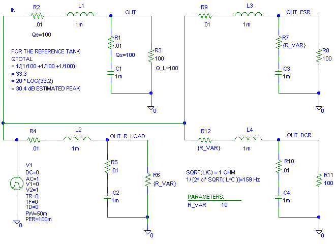
There are four LC tanks shown in the schematic. I purposely left out
the core loss of the inductor and dielectric loss of the capacitor. This
page will be hard enough to understand with out core loss and dielectric
loss muddying the water.
The top left tank is our reference tank. It will always have the same
Q_total of 100 and the same part values. In the other three tanks I will
vary the DCR of the inductor, the ESR of the capacitor or the load resistance
so we can see what happens.
I purposely set the characteristic impedance of the tank (Zo) to 1.
The characteristic impedance of the tank and resonant frequency are given
by
Zo = SQRT( L/C)
wo = 1/ SQRT( L*C) = 2 * PI * fo
Xc = 1/(2 * PI * F * C)
Xl = 2 * PI * F * L
Q_dcr = Zo/ DCR
Q_esr = Zo/ ESR
Q_load = R_load/ Zo <- notice that this is different. Q is
infinite if R_load is infinite. For the others, Q in infinite when the
resistance is zero.
Q_total ~ 1/ ( 1/ Q_dcr + 1/ Q_esr + 1/ Q_load )
At resonance:
Zin ~ = Zo/ Q
Zout ~= Zo * Q
Gain ~= Q
1 mH is 0.1 ohm at 15.9 Hz, 1 ohm at 159 Hz and 10 ohm at 1.59
kHz.
1 mF is 0.1 ohm at 1.59 kHz, 1 ohm at 159 Hz and 10 ohm at 159
Hz.
First lets look at what happens to the frequency response when we vary
the resistors one at a time. First lets set R_VAR = 0.1 and look at the
response.
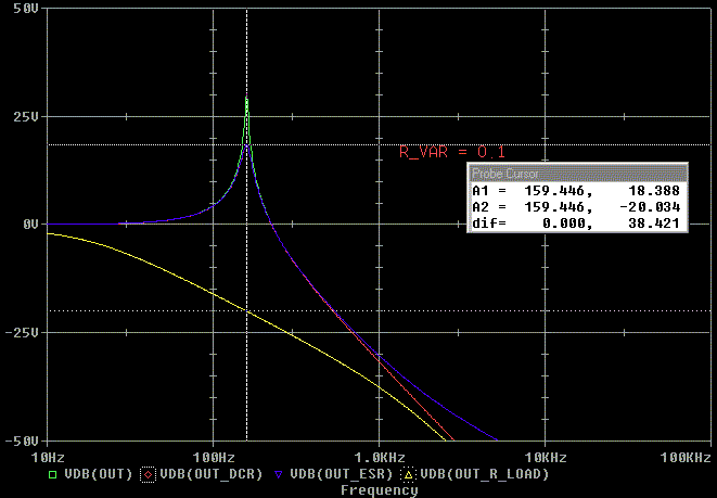
When the load resistor is 0.1 ohm (Q_total ~ 0.0998, 20 log( 0.0998)
= -20 dB), notice how the frequency response is suppressed 20 dB
at the 159 Hz resonant frequency. The frequency response with the ESR =
0.1 and DCR = 0.1 are both nearly the same out to about 1 kHz. Their Q_total
is 1/(1/100 + 1/10 + 1/100) = 8.33 or +18.4 dB.
When the ESR of the capacitor is 0.1, you can see we loose attenuation
above 1 kHz because the circuit effectively now only has one reactive pole
(the inductor) instead of two. This is because the ESR of the capacitor
keeps the impedance of the capacitor from getting lower as the frequency
increases. Sometimes we will care about the change in rate of attention
at high frequencies, sometimes we won't.
When the DCR of the inductor is 0.1, we don't lose high frequency attenuation,
but we lose more low frequency energy.
With R_load = 100 and the DCR = 0.01 we loose 0.00087 dB. As the DCR
increases to 0.1, 1.0, 10 ohms we get 0.0087 db, 0.086 dB, 0.83 dB loss
respectively. This may not seem much, but with R_load = 10 ohm with the
DCR = 0.1, 1.0, 10 ohms the losses become 0.086 dB, 0.83 dB, -6.0
dB respectively. With an 8 ohm speaker the "Damping factor" for 0.1, 1.0
and 10 ohms becomes 80, 8, 0.8 respectively. Again, sometimes we will care
about the DCR loss and sometimes not.
Now lets set R_VAR = 10.

Notice that the output is again 20 dB low when the DCR is set to 10
ohms and that we are losing low frequency energy again.
Notice that with R_load = 10 the peak is again 18.4 dB (20 log [1/(1/100
+ 1/100 + 1/10) ] = 18.4 dB .) We got the same Q of 8.33 from a different
circuit and we got the same peak of 18.4 dB.
Notice that with the ESR = 10, we hardly don't get any high frequency
attenuation. This is because the only reactive element is the inductor.
The ESR effectively hides the capacitor from the rest of the circuit in
this plot. At 1 kHz, 1 mF is -j0.159 ohms. 10 ohms in series with a reactive
0.159 ohms is still just 10 ohms..
How much do we care about these differences? In some circuits we will
care a lot. In others it will be no big deal.
If all of this is happening at 159 kHz instead of 159
Hz, we'll care about the peaking in "R_load" because it can cause circuits
both driving the LC tank and on the output of the LC tank to overload.
The driving circuit can overload from the current draw. The circuit on
the output side can overload because of the voltage peaks.
If this is happening at 159 kHz, the droop in the response at 10 kHz
(equivalent to 10 Hz on the plot) could bother a few meter readers.
Not lets set R_VAR = 1 ohm. One ohm is the characteristic impedance of
our tank.

At our 159 Hz resonant frequency, the peaking is nearly 0 dB (Q total
=( 1/100 + 1/100 + 1/1) = 0.98, 20 log 0.98 = -0.17 dB) for both the DCR
(red) and R_load (Yellow) = 1 ohm. For ESR (blue) = 1 ohm, there is slight
peaking. That is because the cap is starting to drop out of the LC tank
at the same time the tank goes resonant.
Lets look at the peak in the response as we sweep
the variables
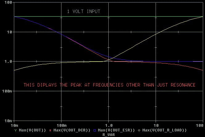
First look at the overall peak. This is the peak at any frequency in
the sweep.
Next lets look at the peak at resonance (159 Hz where the Q equations
work.) Notice that they are different. The Q equations are only good at
the resonant frequency.
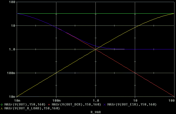
Looking at the plot above, green is our reference Q of 33 (30 dB) and
is not changes with R_VAR.
Red is sweeping the DCR. As the DCR increases, the Q decreases. That
is because more energy is lost as the DCR increases.
Blue is sweeping the ESR. As the ESR increases, the Q decreases but
does not go below 1.
Yellow is sweeping the R_load, As the R_load increases, the Q increases.
That is because less and less energy is lost in the load resistance as
the resistance goes up.
Well "There Ain't No Such Thing As A Free Lunch" or my version "There
Ain't No Such Thing As A Free Variable."
What do we give up as we change part parasitics or the load resistor?
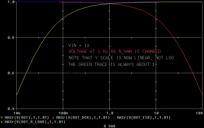
Lets look at what happens at 1 Hz. The ESR doesn't have any effect
at 1 Hz.
The DCR and R_load do have an effect. At low frequencies the DCR and
R_load form a voltage divider and useful power is lost as seen below.
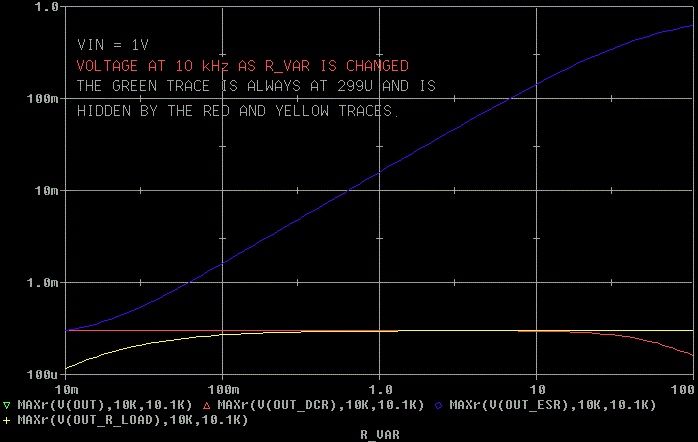
What happens at 10 kHz? Look below.
At 10 kHz the DCR (red) does not have much of an effect because the
impedance of the inductor (2 * pi * 10 kHz * 1 mH = 63 ohms) is greater
than the DC resistance.
R_load (yellow) has some effect, but nothing to get excited about.
The ESR (blue) has a huge effect because at 10 kHz the capacitor is
dominant (the lowest) impedance in the circuit and the ESR is messing with
the impedance of the capacitor ( 1/ [2 * pi * 10 kHz * 1 mF] = .016 ohms.)
Step Responses
Step responses is what we get all excited about. So here are a few.
First with R_VAR = 0.1. Notice with R_load = 0.1, there is no ringing,
but the response never makes it to the applied 1V. Some of the applied
voltage is lost. The green trace is our original high Q tank. The two lower
Q traces for DCR and ESR are on top of each other.

Next lets look at R_VAR = 10. Notice when the DCR = 10 ohms, the output
never makes it to the 1V that is put into the tank.

Now lets look at R_VAR = 1. Wow. Nothing is ringing but the high Q tank.
The outputs are getting pretty much up to the input voltage too. Notice
that the blue trace (ESR) is rising faster than the rest.
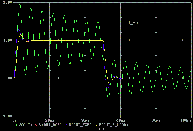
Lets look closer at the rising edge. With the capacitor "hidden" from
the LC tank by its ESR, the capacitor can't attenuate the high frequency
response. This makes the rise time faster. This can be a good thing if
we want the high frequencies. It can be a bad thing if we don't want the
high frequencies.

To be fair. I'll zoom in on the rise times with R_VAR = 0.1 and 10.

Hey, with the ESR = 10 ohms the rise time is even faster meaning less
attenuation from the capacitor than with the ESR = 1 ohm.

How about what the input impedance does with changes
in R_VAR
1 mH is 0.1 ohm at 15.9 Hz, 1 ohm at 159 Hz and 10 ohm at 1.59
kHz.
1 mF is 0.1 ohm at 1.59 kHz, 1 ohm at 159 Hz and 10 ohm at 159
Hz.
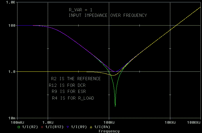
First we'll look at R_VAR = 0.1 (Q_total = 8.33 and 1/ Q_total = 0.12).
Notice that for DCR and ESR = 0.1, the minimum impedance is 0.12 (Zo/
8.33)
For R_load = 0.1 ohm, Q_total = 0.0998 and the equations fall apart
because the capacitor can't do anything against such a small load resistance.
1 mF is 0.1 ohm at 1.59 kHz. At this frequency, the 1 mH inductor is 10
ohms. The capacitor is effectively no longer in the equation.

Next we'll look at R_VAR = 10. When R_load is 10 ohms the equations
work. When the DCR and ESR are 10 ohms the equations fall apart. When the
DCR is 10 ohms the input impedance cannot fall below 10 ohms. When the
ESR is 10 ohms the 1 mF capacitor drops out of the equation near resonance.
1 mF becomes 10 ohms at 15.9 Hz, well below the 159 Hz resonance.
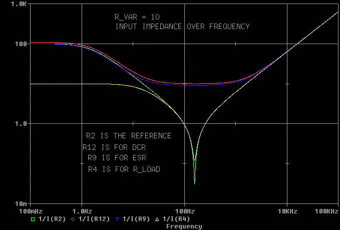
Last we'll look at R_VAR = 1, the low Q case (Q_total = 0.98). Everything
but the reference is well behaved.
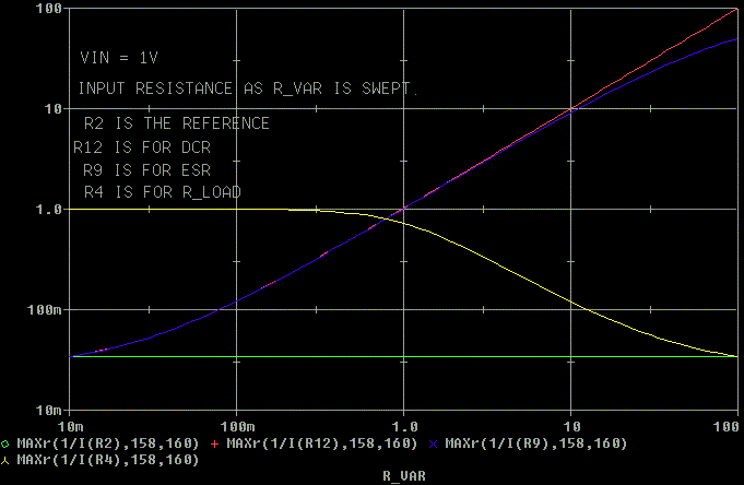
Here is a sweep of the input impedance at resonance with R_VAR varied
from .01 ohm to 100 ohms.
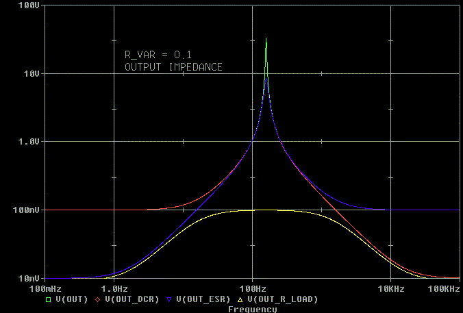
What about the output impedance?
Again we'll look at R_VAR = 0.1. Things get nasty except when the R_load
is swamping everything out.
Notice how at above resonance the ESR sets the output impedance when
the ESR is 0.1 ohms.
Now look at R_VAR = 10 ohms.
1 mH isn't 10 ohms until 1.59 kHz. 1 mF is 10 ohms at 15.9 Hz. So the
DCR hides the inductor and the ESR hides the capacitor from the circuit
at resonance. But with R_load = 10 ohms the output impedance peaks at just
under 10 ohms (at about Q * Zo = 8.33 ohms * 1 ohm = 8.33 ohms)

Now the low Q state with R_VAR = 1 ohms where things behave nicely.
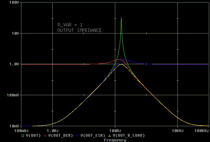
Here's the output impedance at resonance with R_VAR swept from 10 moms
to 10 ohms.
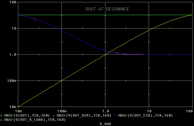
This web page is another web page I wanted to get out fast and is not
as detailed as I'd like. What I want to do next is to add RC damping to
this same tank so we can see the benefits of damping with external elements.
If you have questions or comments, contact me through asylum mail.
Some of the benefits from using RC damping instead of changing the DCR,
ESR or R_load
1. That the low frequency insertion loss and damping factor do not
change like they will if the DCR of the inductor is increased.
2. If this is a transformer, the DCR of the primary can be kept low
so that there is less induced distortion from the core distortion. With
a zero ohm source impedance and with zero ohms DCR, the core magnetization
current can do anything it wants and the output voltage won't have any
distortion. We don't have zero ohms DCR nor zero ohms plate resistance,
so we have to manage the core distortion, source impedance and DCR wisely.
3. By controlling the damping with an external RC from the transformer,
one transformer can be tuned for may different types of tubes.
First version 16 Mar 03 Last change 18-Mar-03
OK,. I'll explain the pun
"Tank Q" = "Thank you"
The response to "Thank you" is "You're welcome."


