This page is: "4. Paramour: Stock Output Transformer, Stock
Choke, Sino 2A3 tubes,
Left Amp, 10% distortion pictures, distortion curves."
This involves working with high voltages, attempt
these changes at your own risk.
Many people refer to magnetics as "iron" no
matter what the magnetics are made of.
1. Paramour: Top Level Link.
10% Distortion Tables vs Frequency. Output impedance vs Frequency.
2. Paramour:
Stock Output Transformer, Stock Choke, AVVT 2A3 M tubes,
Right Amp, 10% distortion pictures, No distortion curves.
This link opens a new window so you can compare it
to other pages.
3. Paramour: Stock
Output Transformer, EXO-04 Choke, AVVT 2A3
M tubes,
Right Amp, 10% distortion pictures, distortion curves.
4. Paramour: Stock Output
Transformer, Stock Choke,
Sino 2A3 tubes,
Left Amp, 10% distortion pictures, distortion curves and many other
pictures.
5. Paramour: Stock
Output Transformer, Stock Choke,
AVVT 2A3 tubes,
Left Amp, 10% distortion pictures, distortion curves.
6. Paramour:
EXO-45-VS Output Transformer, Stock Choke, AVVT 2A3 tubes,
Left Amp, 10% distortion pictures, distortion curves,
50Hz 100 Hz distortion curve comparison.
7. Paramour:
EXO-45-VS Output Transformer, EXO-04 Choke, AVVT 2A3 tubes
Right Amp, 10% distortion pictures, distortion curves.
Stock Output Transformer
Stock Plate Choke
Stock SINO 2A3 tubes.
Pictures taken at 10% distortion into 8.45 ohms (Left
Amplifier).
An old HP 334 was used to measure the distortion.
Added 04/28/01 Updated 04/28/01
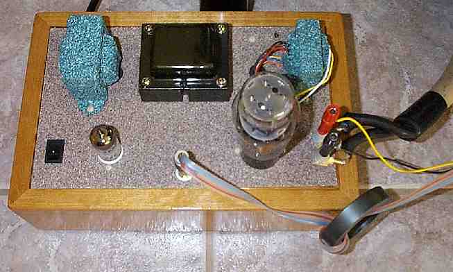
The amp under test:

This is the left channel with the stock Paramour magnetics with a SINO
2A3 at 10 kHz, 2V/ div, 10 usec/ div, 10% distortion. (6.3 V rms)

This is the left channel with the stock Paramour magnetics with a SINO
2A3 at 1 kHz, 2V/ div, 100 usec/ div, 10% distortion. (6.27 V rms)

This is the left channel with the stock Paramour magnetics with a SINO
2A3 at 100 Hz, 2V/ div, 1 msec/ div, 10% distortion. (5.25 V rms)

This is the left channel with the stock Paramour magnetics with a SINO
2A3 at 50 Hz, 2V/ div, 2 msec/ div, 10% distortion. (3.81 V rms)

This is the left channel with the stock Paramour magnetics with a SINO
2A3 at 20 Hz, 2V/ div, 5 msec/ div, 10% distortion. (1.57 V rms)

Notes for Chart 2:
1. I took these distortion measurements with a Heathkit Sinewave generator
that was sending 1.0 % distortion at 100 Hz and 1.5 % distortion at 50
Hz to the Paramour before the Paramour added any distortion of its own.
2. I could manually null the HP334A I was using better than the autonull
would work.
Chart 2: Paramour with stock iron: Distortion vs Output Power into 8.45
ohms on 8 ohm tap with Sino 2A3 output tube. (Left Amplifier)

Lets look at the 10 kHz picture again:
This is the left channel with the stock Paramour magnetics with a SINO
2A3 at 10 kHz, 2V/ div, 10 usec/ div, 10% distortion, 8.45 ohm load on
8 ohm output tap. (6.3 V rms)

This is what the plate and grid are doing in this while the output is
putting out 6.3V into an 8.45 ohm load.

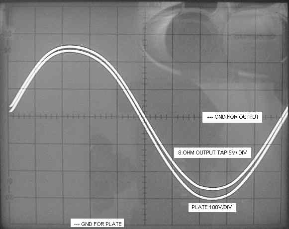
With 6.3V into a 8.45 ohm load on the 8 ohm tap, this is what the plate
and 8 ohm tap look like. The output voltage lags the plate voltage because
of leakage inductance in the transformer.

This is what happens when you remove the 8.45 ohm load on the output.
The output voltage goes up to 10V rms at 10 kHz.

We can see from the two pictures above that we can get the voltage
out of the magnetics at 10 kHz, we just can't deliver the current.
(I bumped the grid's offset voltage when I adjusted the time scale.
That caused the GND to for the grid to move.)
At 10V no load output 10 kHz, this is what the plate and 8 ohm output
tap looks like:

The phase lag in the output voltage goes away because the impedance
of the leakage inductance is now small compared to the no load impedance
on the output.
Lets look at the 50 Hz picture again:
This is the left channel with the stock Paramour magnetics with a SINO
2A3 at 50 Hz, 2V/ div, 2 msec/ div, 10% distortion, 8.45 ohm load on 8
ohm tap. (3.81 V rms)

Here is the plate and grid voltage for the 50 Hz 3.81 V rms output into
8.45 ohm waveform above.

Here is the plate and output voltage for the picture above. (50 Hz,
3.81V into 8.45 ohms)
Note that I changed the gain of the output from 2V/ div down to 5V/
div.

Now just for kicks, lets keep the grid voltage the same and pull the
8.45 ohm load off the 8 ohm output.
50 Hz with 5.38V rms output on the unloaded 8 ohm output tap:

That is some serious distortion. It looks like we are running out of
plate current at the same time we are saturating the output transformer.